Knowledge
Flatness Measurement Methods Compared: Plate, CMM, Vision, Confocal
There is no such thing as a dedicated flatness gauge. Flatness is a derived quantity, so choosing how to measure it really means choosing how to obtain that set of points reliably and efficiently.
The routes differ substantially in measurement range, achievable point density, tolerance of difficult materials and time per part. Getting it wrong costs more than money. The usual outcome is measuring without being able to use it: numbers that drift, lots that cannot be compared, and different people computing different results. Here are the five routes and their boundaries.
Route one: surface plate with feeler gauge or indicator
Place the part on a reference plate, either slide feeler gauges under it or traverse an indicator across the surface and take the difference between the highest and lowest indication.
Its advantages are real: minimal cost, no power required, and usable right on the shop floor. The limits are equally real. It yields a maximum gap or an indication spread, not the shape of the surface. It depends heavily on operator feel and consistency. It risks deforming compliant or thin-walled parts. And it produces nothing you can trace later. Use it for rapid screening, not as the sole basis for disposition, and certainly not as the data source for process improvement.
Route two: coordinate measuring machine
A contact probe traverses a planned path and the software fits the result. This is the most established route in traditional metrology.
It offers the best combination of accuracy and traceability, works well as an arbitration method, and can evaluate a wide range of geometric tolerances in one setup. Against it: point-by-point acquisition means more points cost more time, probe force still affects soft materials, temperature requirements are strict, and capital plus maintenance cost is significant. Reserve it for first-article evaluation, dispute arbitration, and cases that require formal traceability.
Route three: vision and one-shot image measurement
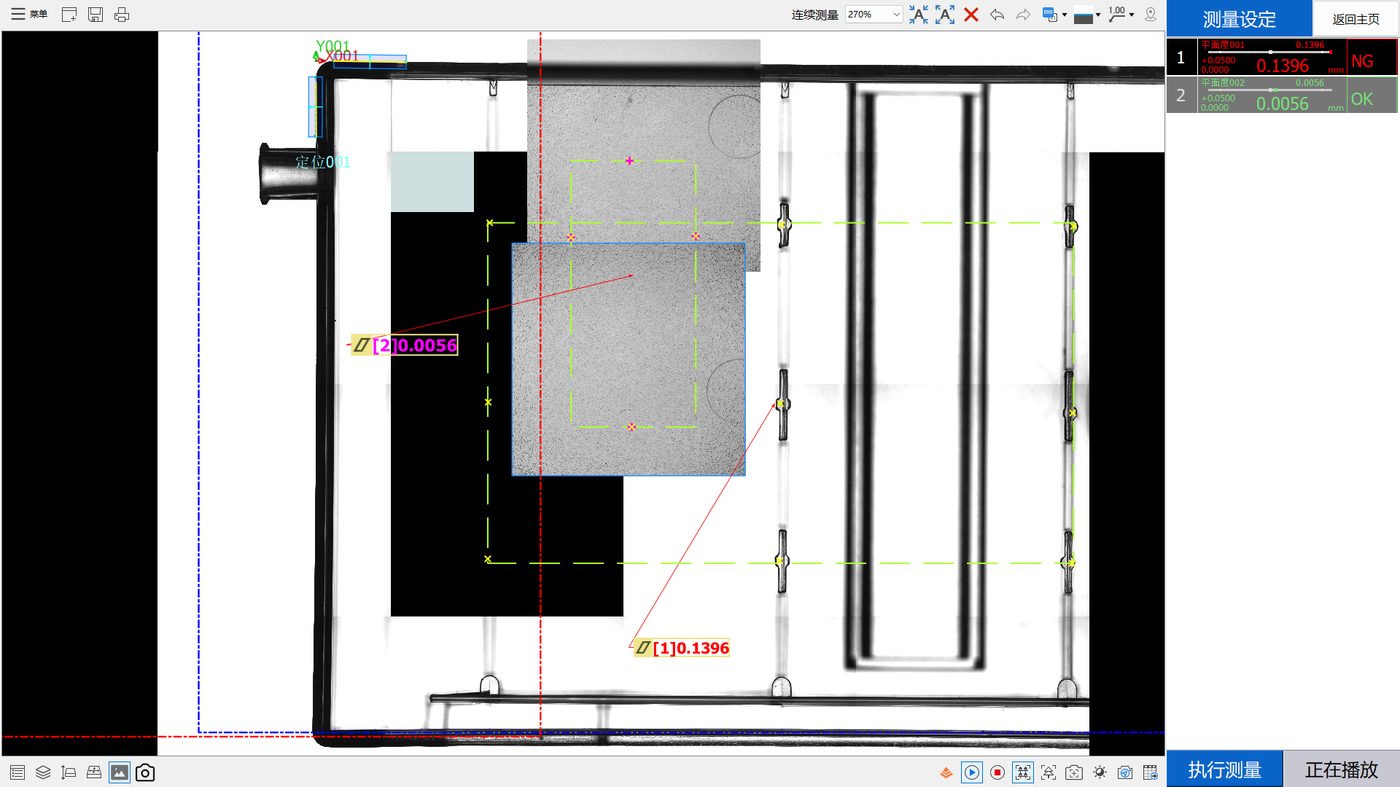
An area camera captures the whole field at once, the software extracts large numbers of edges and features, and automatic recognition and autofocus complete many features in one cycle.
The advantage is acquisition efficiency: one shot covers many features, which suits high-mix batch work and repeat measurement. It is non-contact, so no probe deflection, and reporting is highly automated. The limitation is that two-dimensional imaging carries no height information by nature, so flatness requires an additional height or 3D acquisition means; transparent and highly reflective surfaces also need deliberate illumination engineering. POMEAS positions the MX series as a multi-sensor platform to supply that missing third dimension.
Route four: chromatic confocal displacement sensing
A broadband source is dispersed so that each wavelength focuses at a different axial distance. Only the wavelength focused exactly on the surface returns efficiently, and the peak of the returned spectrum encodes the distance.
The strengths are high resolution at a very small spot, tolerance of transparent and highly reflective surfaces, and the ability to focus separately on the top and bottom surface of transparent material - the physical basis for thickness measurement on clear parts. The limits are that it is single-point: covering large areas needs a motion stage or an array of heads, and the short reference distances constrain fixture design.
The POMEAS SFS family shows the usual range-versus-precision trade off. Documented figures: SFS-D108 has a +/- 0.05 mm range with 3 nm stated repeatability; SFS-D410 runs +/- 0.2 mm at 12 nm; SFS-D606 runs +/- 0.3 mm at 16 nm; SFS-D1220 runs +/- 0.6 mm at 30 nm; SFS-D2615 runs +/- 1.3 mm at 50 nm. Larger ranges generally come with looser stated repeatability, so choose from the height variation you actually have to cover.
Route five: integrated height measurement
Mounting a height sensor directly into an image measurement system combines 2D dimensions and height data in one workflow. The value here is not a single-point performance record - it is embedding flatness evaluation into an existing batch dimensional inspection, eliminating a second clamp and a second trip.
Watch the boundary carefully. Height measurement is not standard across a whole series. Within the IMAGE 3 family, only the MAX and MAX2 models are documented as supporting 8055 point spectral confocal height measurement, at a 55 mm working distance and +/- 3 mm range. Always confirm the specific model and sensor configuration rather than assuming a family shares one set of capabilities.
Route comparison
| Route | Information obtained | Cycle time | Material tolerance | Typical use |
|---|---|---|---|---|
| Plate and feeler gauge | Gap or indication spread | Fastest | Limited by contact deflection | Shop-floor screening |
| Indicator traverse | Indication spread | Fast | Same limitation | Single-part quick check |
| CMM | High accuracy point set | Slower | High, bounded by probe force | First article, arbitration, traceability |
| Vision one-shot | 2D feature point cloud | Fast | Needs illumination engineering | Batch 2D dimensions |
| Chromatic confocal | High resolution single point distance | Medium | Tolerant of clear and glossy | Height, step, thickness |
| Multi-sensor integrated | 2D plus height combined | Fast | Depends on combination | Batch combined dimensions and flatness |
This table is qualitative, and its job is to narrow the field. Whether a specific configuration meets a specific tolerance must be confirmed by measuring actual samples on that configuration.
Three recurring selection mistakes
One: working backwards from a headline specification. Seeing 3 nm repeatability and assuming it solves everything, while overlooking that the range is +/- 0.05 mm. Range has to cover the real height variation first; precision only becomes meaningful after that.
Two: evaluating the instrument instead of the scheme. Point count matters, but which points are taken and how they are fitted matter just as much. The same hardware under different conventions can return substantially different flatness values.
Three: ignoring cycle time and the data loop. Something that measures beautifully in the lab may not keep pace on the line, or may produce numbers nobody retains. A usable scheme has to answer two questions at once: how often does a result appear, and where does it go.
Frequently asked questions
Can 2D imaging measure flatness on its own?
No. Two-dimensional imaging carries no height dimension, so flatness cannot be evaluated from it directly. Completing the job on one platform requires additional height acquisition - a point spectral confocal module, a white-light confocal head, or another 3D sensing method. Always confirm with the supplier whether the specific model includes it.
Contact or non-contact - how do I choose?
Start from stiffness and surface sensitivity. Soft, thin-walled, easily marked or high-finish surfaces favour non-contact. Rigid parts indifferent to a modest probe force can benefit from the traceability and low single-point uncertainty that contact still offers. Cycle time and budget decide the rest.
Why is confocal recommended for transparent parts?
Because it determines distance from the spectral peak rather than from an image intensity edge, and because it can focus separately on the top and bottom surfaces of a transparent material while never touching it. That combination suits height and thickness work on clear parts. Whether it suits your specific part is still a sample-test question.
What does reference distance mean?
It is the nominal standoff from sensor head to target that the installation should maintain. It determines the space and travel you must design for and bounds what distance remains within measuring range. Confirm the line can reliably hold that standoff before selecting a model.
Does a large part necessarily need many sensors?
Not necessarily. Single head plus motion stage and a synchronised sensor array are both valid. The former costs less and runs slower; the latter runs faster and costs more in hardware and synchronisation. Area, required point density and cycle budget decide it. Multi-channel controllers support several heads at once, though per-channel sampling rate generally falls as channels are added.
What should I send the supplier before quoting?
Real parts or drawings, the areas to evaluate with their tolerances, material and surface condition, target cycle time, and the form you want the data in. The more complete the brief, the closer the first proposal lands, and the fewer round trips of samples.
Related reading
Principle-level detail for each route is available in the articles on non-contact displacement comparison, the confocal principle, and how to read an accuracy specification for instant measurement. Transparent parts have dedicated coverage elsewhere in this series.
Related products and configuration notes
- POMEAS MX Automatic Vision Measuring Machine - Multi-sensor platform combining optical measurement with optional sensing modules
- POMEAS IMAGE 3 Instant Vision Measuring System - MAX and MAX2 are documented for point spectral confocal height measurement at 55 mm working distance
- SFS-D108 chromatic confocal sensor - +/- 0.05 mm range; stated repeatability 3 nm - the highest resolution tier of the family
- SFS-D1220 chromatic confocal sensor - 20 mm reference distance, +/- 0.6 mm range, stated repeatability 30 nm
Related reading
- Transparent Plastic Part Flatness Inspection: What Two Data Sets Actually Show
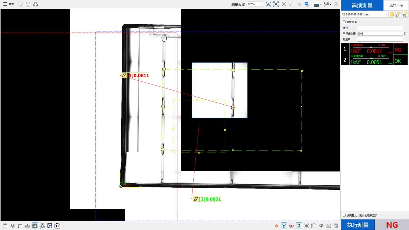
- Two Flatness Zones, Two Opposite Verdicts on the Same Part
- Flatness Out of Tolerance: A Troubleshooting Path That Actually Works
- What Flatness Really Means, and What It Is Often Confused With
- Repeatability Is Not Accuracy: Reading Range, Sigma and Cpk Honestly
- How to Choose Flatness Inspection Equipment: A Five-Step Reverse Method
- Point Spectral Confocal for Transparent Plastics: Benefits, Limits and Four Mistakes
- Multi-Point or Single-Point Flatness: Choosing How to Collect the Points
- Where Warpage in Injection Moulded Parts Comes From
- Turning Inspection Data into Decisions: Four Stages of Refinement
Instruments for Each Method
The comparison above separates contact, optical and interferometric methods. These are the products POMEAS builds in two of those categories.
- POMEAS WLI100 3D White Light Interferometer — sub-0.2 nm vertical resolution over a 0–10 mm Z range for areal topography
- POMEAS IMAGE 3 Instant Vision Measuring System — one-shot stage: 18 × 18 mm to Ø100 mm fields, repeatability from ±0.25 µm depending on model
- Single-Channel Confocal Displacement Sensor Controller — one measuring head, the entry configuration for single-point thickness and position
Comparing models side by side? check the white light interferometer specification.
Tell us the tolerance, the area to be covered and whether the surface is reflective, and we will point to the method that will not fight the material. Send the details.

Subscribe to Our Newsletter
Simply enter your email to receive the latest news and insights from Pomeas. Stay connected with Pomeas and be the first to discover new innovations in optical excellence.


