Knowledge
What Flatness Really Means, and What It Is Often Confused With
Flatness is the most basic geometric tolerance and also the one that looks simplest while arguing hardest. Everybody believes they know what it means, right up to the moment a report lands on the table and the conversation slides into where the number came from.
The reason is structural. Flatness cannot be read off an instrument the way a diameter can. It is a derived value, produced by sampling points on a surface, fitting an ideal plane under some agreed rule, and measuring the departure from it. Different rules give different numbers for the same surface.
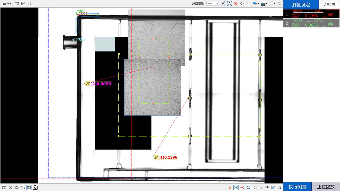
The definition
Under the standard framework for geometrical tolerancing, flatness controls the form error of a single surface. Its tolerance zone is the region between two parallel planes separated by the tolerance value t. Every point of the actual surface must lie between those two planes for the requirement to be met.
Two details in that definition get overlooked. First, it constrains the shape of one surface in isolation - it says nothing about relationships to other features. Second, it requires no datum. Those two properties are precisely what separates flatness from several neighbouring controls.
Why flatness must be fitted before it can be quantified
What a measuring system actually captures is a set of discrete coordinates. Turning that set into a flatness number takes three steps.
| Step | What happens | The key choice |
|---|---|---|
| Sampling | Acquire points on the surface under some strategy | Coverage, density, and how outliers are handled |
| Fitting | Fit an ideal plane through the points | Minimum zone, least squares, or another convention |
| Evaluation | Compute maximum departure from that plane | Direction and how departures are combined |
Every step contains a choice, and each choice moves the final number. That is why two competent systems can return different values for the same part without either being wrong - the evaluation convention differs. A result with real traceability therefore has to record sampling strategy and fitting rule alongside the number, or it cannot be re-derived.
The four most common confusions
Flatness versus parallelism
Flatness governs the form of one surface and needs no datum. Parallelism governs the orientation of one surface relative to another - the datum. A part can have excellent flatness and fail parallelism (two perfectly flat faces that are not parallel to each other), and equally have good parallelism while every individual face is twisted. Whether a datum symbol appears on the drawing is the direct tell.
Flatness versus coplanarity
Coplanarity asks whether several separate features - a row of leads, a set of mounting bosses - lie in a common ideal plane. Its subject is the mutual agreement of multiple features. Flatness concerns form within one continuous surface. Both require fitting, but they address different objects, and mixing them means treating a multi-feature problem as a single-surface problem, or vice versa.
Flatness versus warpage
Warpage belongs to process vocabulary. It describes the phenomenon of deformation during forming or machining, and its emphasis is cause. Flatness belongs to technical vocabulary and its emphasis is the measurable result. The two get used interchangeably in conversation, but not in documents: use warpage to describe what is happening and flatness to write the verdict.
Flatness versus profile of a surface
Profile of a surface constrains departure from the theoretically exact contour, and depending on how it is applied, can control form and also orientation or location. Flatness only controls form - it says nothing about where the surface should be. When position matters as much as shape, flatness alone is not sufficient.
Why one drawing is often not enough
Disputes rarely happen at the level of definitions. They happen at the level of which area is being judged. A drawing carries one flatness callout, but the part may contain several functionally distinct areas: a sealing face, a mating face, a cosmetic face and non-critical regions. Their sensitivity to form error is nowhere near equal.
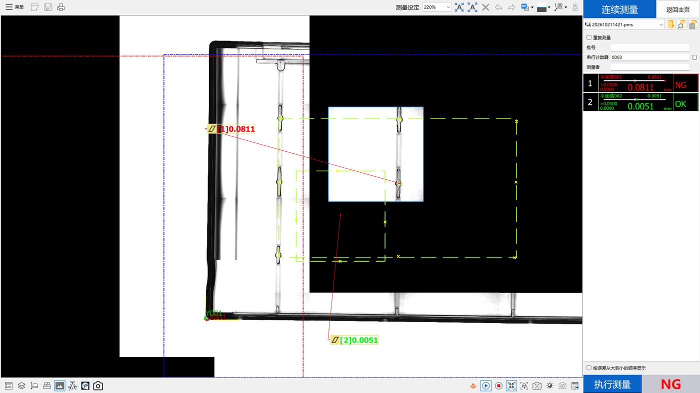
Covering all of them with a single part-wide callout typically produces a measured value that neither confirms nor rejects any particular process judgement. The workable alternative is to define several evaluation zones by function, each with its own tolerance band and its own measurement method. We saw a clear example of this in the case data behind this series: two zones on the same part averaged more than twentyfold apart, so any single global value would have been meaningless.
Four suggestions for writing a flatness requirement
One, define the boundary of the zone. Use a drawing, not prose, and say explicitly what is excluded. Two, state the evaluation convention so it is not debated afterwards. Three, separate first-article requirements from in-process sampling - the frequency and the focus differ. Four, if relative position also matters, add parallelism or another related control instead of expecting flatness to carry it.
Do those four things and the number in the report becomes a basis for communication rather than a starting point for disagreement.
Frequently asked questions
Does flatness need a datum?
Under the standard tolerancing framework, flatness is a form control applied to a single feature and requires no datum. If your intent is to control this face relative to another, you need parallelism or another datum-referenced control. The presence of a datum symbol is the shortest way to tell which one you wrote.
Why do two systems give different values for the same part?
The usual causes are different sampling strategies - point count and distribution - different fitting conventions, and different treatment of outliers. These are differences in evaluation, not necessarily errors. To make results comparable, both sides must agree on those three settings and record them.
How much do minimum zone and least squares differ?
They optimise different objectives and generally return different results for the same point set, with the gap depending on how the points are shaped. Which is why the convention has to be agreed when the program is built rather than after a dispute arises.
Should a drawing say how many points to take?
It is strongly advisable. Sampling strategy directly determines how stable and representative the result is. A zone sampled at five points is not evidence of the same quality as the same callout sampled at fifty. Recording point count and distribution in the working instruction removes a great deal of downstream argument.
Can the part's own weight affect the reading?
Yes. Large thin-walled parts can deflect under gravity by amounts comparable to the tolerance band depending on orientation. The measurement posture should simulate actual assembly or service conditions and be specified consistently, otherwise results from different operators are not comparable.
Can plastics and metals carry the same flatness callout?
The number can be identical, but the evaluation conditions generally cannot. Plastics change shape over time through stress relaxation and moisture uptake, so the reading moves. Alongside the tolerance value you need to specify when the part is measured and under what conditions, or "when to measure" becomes the next argument.
Related reading
The real example of zone-level divergence is covered in the second article of this series; the measurement routes are compared elsewhere; and the reading of scatter-related indicators is treated in its own article.
Related products and configuration notes
- POMEAS MX Automatic Vision Measuring Machine - Documented for 2D/3D dimensions, form tolerance, cross-section profiles and thickness
- POMEAS IMAGE 3 Instant Vision Measuring System - Multi-object extendable to 300 features per program for larger samples
Related reading
- Transparent Plastic Part Flatness Inspection: What Two Data Sets Actually Show
- Two Flatness Zones, Two Opposite Verdicts on the Same Part
- Flatness Out of Tolerance: A Troubleshooting Path That Actually Works
- Flatness Measurement Methods Compared: Plate, CMM, Vision, Confocal
- Repeatability Is Not Accuracy: Reading Range, Sigma and Cpk Honestly
- How to Choose Flatness Inspection Equipment: A Five-Step Reverse Method
- Point Spectral Confocal for Transparent Plastics: Benefits, Limits and Four Mistakes
- Multi-Point or Single-Point Flatness: Choosing How to Collect the Points
- Where Warpage in Injection Moulded Parts Comes From
- Turning Inspection Data into Decisions: Four Stages of Refinement
Related POMEAS product categories
The hardware referred to above is grouped into the following categories on the product side, with the specifications and model list for each range.
- 3D White Light Interferometer / Optical Surface Profiler — 3D white light interferometer profilers for roughness, step height and flatness.

Subscribe to Our Newsletter
Simply enter your email to receive the latest news and insights from Pomeas. Stay connected with Pomeas and be the first to discover new innovations in optical excellence.


