Knowledge
AOI Lens Upgrade on an Installed PCBA Machine: 17.3 × 17.3 mm to 12 × 12 or 8 × 8 mm
An AOI lens upgrade is usually the cheapest way to buy detail on a machine you already own — provided the optical arithmetic is finished before anyone quotes a lens. This article works through one real inquiry: a European electronics manufacturer running a PCBA AOI station with a 0.25X telecentric lens, asking whether the 17.3 × 17.3 mm field of view can be reduced to 12 × 12 mm or 8 × 8 mm while keeping the existing camera and the existing multi-colour light.
Be clear about what this document is. It is a solution proposal derived from a customer inquiry, not an installation case and not a verified result. No POMEAS lens has been fitted to that machine, and no measurement has been taken on it. Every number below is either read off the customer's own hardware, read from a POMEAS product record, or marked derived with the arithmetic written out. Where a value is unknown, it stays unknown and is listed as something to confirm.
What This Customer Actually Asked For
The constraint set is narrow, and that is what makes the problem interesting. The customer does not want a new AOI machine. They want to keep the camera, keep the multi-colour ring light, keep the Z-axis column and the conveyor interface, and change only the optics so that the inspection software sees a smaller area with more detail per millimetre.
The hardware facts readable from the customer's own photographs are these, and only these:
- The lens barrel is engraved 0.25X with W.D. 150 mm.
- The iris ring is marked 8 / 11 / 16 / 22, so the existing lens is adjustable in aperture.
- The camera is a compact industrial body. No model marking is legible, so the sensor format, resolution and pixel pitch are UNKNOWN.
- A segmented multi-colour ring light with a hexagonal honeycomb diffuser is bracketed directly under the lens, close to the workpiece.
- A ball screw and linear guide drive the whole camera-plus-lens assembly vertically for focus.
The target is stated in the inquiry as two options: 12 × 12 mm or 8 × 8 mm. Both are square. The current 17.3 mm field is also treated as square in the customer's own description. That square assumption matters later, because a 4:3 or 16:9 sensor cannot deliver a square field without either cropping pixels or accepting an asymmetric image circle.
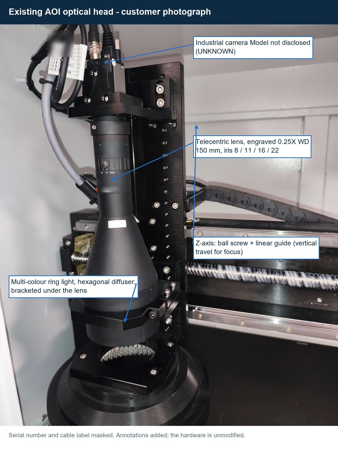
Figure 1 — The customer's existing AOI optical head. Serial number and cable label masked; annotations added, hardware untouched.
Everything downstream depends on one unmeasured quantity, and the next section is about extracting it from what is already known rather than from what we would like to be true.
Work Backwards First: What Is Your Effective Image Width?
Virtually every lens selector on the internet runs the same direction: you enter the sensor width, divide by the magnification, and read off the field of view. That direction is useless here, because the sensor width is exactly the value we do not have. So run it backwards.
The relation is FOV = W / M, where W is the width of the sensor area actually used by the imaging software and M is the lens magnification. Rearranging:
W = FOV × M = 17.3 mm × 0.25 = 4.325 mm (derived)
That 4.325 mm is the single most useful number produced so far, and it is also the easiest one to misread. It is the effective image width — the slice of sensor that the AOI software is actually using — and it is not the sensor format width. The distinction is not pedantry. 4.325 mm is smaller than the 4.8 mm short side of a 1/3″ sensor, which admits at least two very different explanations:
- The camera has a 1/3″-class sensor and the software applies a small region-of-interest crop, or
- The camera has a larger sensor and the software crops a square window out of it, because the inspection area is square and the extra pixels on the long axis are discarded.
The two explanations lead to completely different lens specifications, so this must be settled by the customer's camera datasheet before a lens is chosen. Until then, W = 4.325 mm is a working value, flagged as an assumption, and the rest of this article carries it as one.
If you would rather run the forward calculation yourself for a different sensor, the site's field-of-view and pixel-size calculator covers the standard cases; this article deliberately does not repeat that arithmetic, because the interesting direction here is the reverse one.
The Magnification You Actually Need
Hold W constant at 4.325 mm and solve for the magnification each target field requires. This is the whole answer to the question “what magnification do I need for a 12 mm field of view”:
| Target field | Required magnification M = W / FOV | Magnification ratio relative to the current 0.25X lens |
|---|---|---|
| 17.3 × 17.3 mm (current) | 0.250X (engraved) | 1.000× (reference) |
| 12 × 12 mm | 0.360X (derived) 4.325 / 12 = 0.360 | 17.3 / 12 = 1.442× (derived) |
| 8 × 8 mm | 0.541X (derived) 4.325 / 8 = 0.541 | 17.3 / 8 = 2.163× (derived) |
Read the two right-hand columns as two different things, because this is where most published upgrade advice goes wrong. 0.360X and 0.541X are absolute lens magnifications — the number you would look for on a datasheet. 1.442× and 2.163× are ratios: they say the new lens must magnify 1.442 times or 2.163 times as much as the current 0.25X lens. A ratio of 1.442× is not a lens you can order, and writing “you need a 1.4X lens” would be a factual error that any optical engineer would catch immediately.
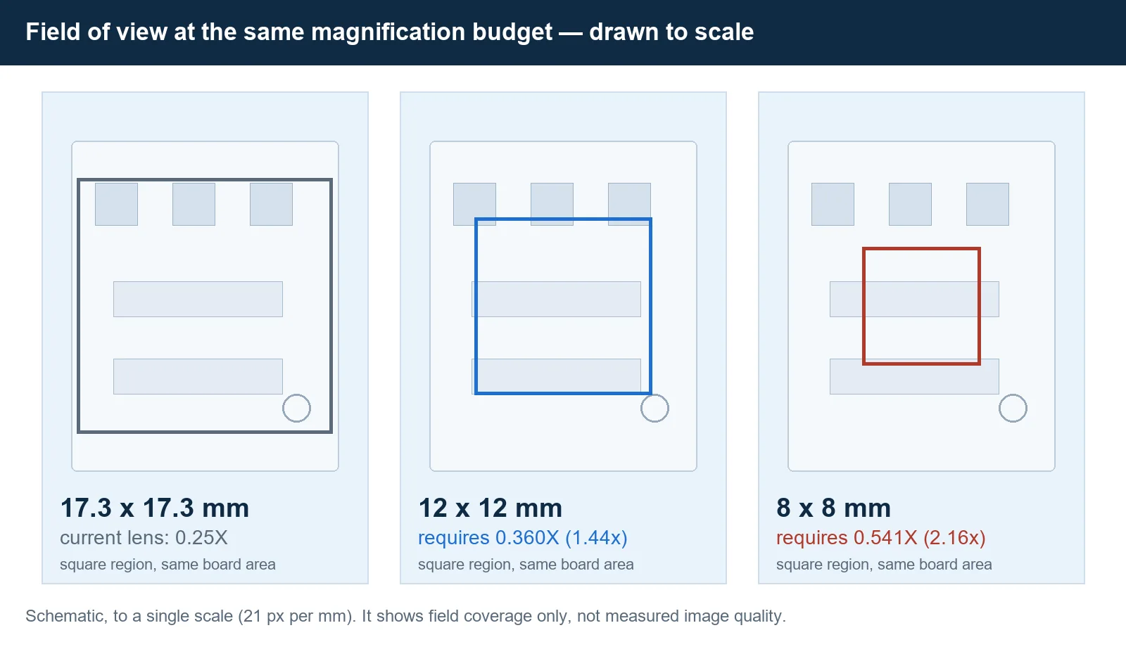
Figure 2 — The three fields drawn to one scale over the same board area. The squares show coverage only; they say nothing about image quality.
Why Cropping the ROI in Software Does Not Add Detail
Before spending money, kill the free option properly. Almost every AOI package lets the operator shrink the region of interest, and the first instinct is that a smaller ROI means a closer look. It does not.
What matters is object sampling: the physical size on the board that one pixel represents. It is calculated as
object sampling = FOV / number of effective pixels across that FOV
Cropping the ROI reduces the field of view and reduces the pixel count by exactly the same proportion. The quotient does not change. You have taken a smaller window of the same image, not a sharper one. The same logic applies to digital zoom, which merely re-samples pixels that already exist.
There are exactly two routes to genuinely more detail:
- Raise the optical magnification. Keep the pixel count and shrink the field, so each pixel covers less board.
- Use a camera with smaller pixels. Keep the field and increase the pixel count, so each pixel again covers less board.
The customer has chosen route one by asking to keep the camera. That is a legitimate choice, and it has a measurable payoff in relative terms: at a 12 mm field the pixel density per millimetre of board becomes 1.442 times the present value, and at 8 mm it becomes 2.163 times (derived). Only relative figures are given here, and that is deliberate — the camera's pixel count is unknown, so any statement in micrometres per pixel would be invented. Once the customer supplies the sensor resolution, the absolute value follows from the formula above in one step.
One more consequence is worth stating in advance: finer sampling only helps if the modulation transfer of the new lens at that sampling rate is adequate. A lens that out-resolves the sensor is wasted; a sensor that out-resolves the lens produces soft pixels regardless of how small the field is.
Route A — A Fixed Telecentric Lens
A fixed telecentric lens is the conservative answer. It is mechanically simple, it has no moving parts to recalibrate, and it keeps the property that made the existing lens a reasonable choice in the first place: the magnification does not change when the workpiece moves in and out of focus, so dimensional measurements stay honest across a board with components of different heights.
Three catalogue focal lengths bracket the requirement, and their real numbers show the shape of the problem:
| Model | Magnification | FOV on the assumed W = 4.325 mm | Working distance | Depth of field | Max sensor | Resolution |
|---|---|---|---|---|---|---|
| PMS-LTCM03-110 | 0.3X | 14.4 mm (derived) | 110 mm | 4.4 mm | 2/3″ | 11.18 µm |
| PMS-LTC05-40 | 0.5X | 8.65 mm (derived) | 40 mm | 1.6 mm | 1/2″ | 6.7 µm |
| PMS-LTC1-85 | 1.0X | 4.3 mm (derived) | 85 mm | 1.00 mm | 2/3″ | 8.39 µm |
Look at what the catalogue does not contain. The 8 mm target needs 0.541X, and 0.5X lands within three quarters of a millimetre of it — close enough to accept, or to trim by adjusting the software's effective width. The 12 mm target needs 0.360X, and there is nothing there: 0.3X overshoots to 14.4 mm, 0.5X undershoots to 8.65 mm. That gap is the single most important finding in this analysis, and it is the kind of finding that only appears once you have computed W instead of assuming a sensor format. For 12 mm on a 4.325 mm effective width, the honest answer is either a non-standard magnification or a two-lens arrangement, and it must be quoted as to be confirmed rather than guessed.
The wider catalogue, including long-working-distance and high-resolution variants, is listed on the telecentric lens range page. Note also the resolution column. These figures are the lens's own imaging limit, and they interact with the sampling question from the previous section: pushing the field down without checking this number is how upgrades end up with more pixels and no more information.
Route B — A Motorized Zoom Lens
The alternative is a motorized continuous zoom lens, which replaces the fixed 0.25X with a range and lets the machine choose a field per inspection step instead of per hardware build. The PMS-LZ-650104 0.7X–4.5X motorized continuous zoom lens covers a 6.5:1 ratio at a working distance of 82 ± 2 mm on a 2/3″ image circle, with 3.95 µm resolution and 0.001% distortion. The 12.5:1 motorized zoom for automated inspection stretches the range to 0.58X–7.5X at 77.4 ± 2 mm. A third option, the 4K zoom lens for 1-inch sensors, runs 0.68X–5.0X at 80 mm.
Two consequences of choosing this route are frequently underestimated at quotation stage.
First, zoom changes the relationship between magnification and position, not just the magnification. On a fixed lens you focus once. On a motorized zoom the magnification setting and the focus position are coupled, so every magnification step needs its own focus calibration, and the calibration has to be repeated whenever the working distance shifts. The engineering detail of how that is managed without stopping the line is covered in the article on magnification changes during AOI inspection; it is not repeated here.
Second, a motorized zoom is an electromechanical subsystem, not a piece of glass. The LZ-650104 uses a DC servo with closed-loop feedback and a 9-pin RS-232 interface, with RS-232 or USB available. That means power, a communication path into the AOI software or PLC, and a magnification read-back that the inspection recipe can trust. If the software cannot read back which magnification is active, every measurement result loses its traceability. This is a software integration task with a schedule, not an accessory purchase.
The full range, including manual and motorized bodies, is on the zoom lens range page.
Route A vs Route B: What Changes on This Machine
Both routes are technically defensible. What separates them is not optical quality in the abstract but the amount of the existing machine that has to be rebuilt. The comparison below is restricted to this installation, at these three fields, on the assumed effective width.
| Dimension | Route A — fixed telecentric | Route B — motorized zoom |
|---|---|---|
| Magnification delivered | One fixed value per lens (0.3X / 0.5X / 1.0X) | Continuous range (0.7X–4.5X, 0.58X–7.5X or 0.68X–5.0X) |
| Reaches 12 mm (0.360X) | No standard step; needs custom or two lenses | Yes, if the range starts low enough for the assumed W |
| Reaches 8 mm (0.541X) | Yes, 0.5X gives 8.65 mm | Yes, within range |
| Keeps the 17.3 mm wide view | No — the fixed lens must stay or be swapped | Only if the wide end reaches 17.3 mm, which depends on W |
| Working distance | 40 mm / 85 mm / 110 mm | 77.4–82 mm |
| Depth of field trend | 4.4 mm at 0.3X, 1.6 mm at 0.5X, 1.00 mm at 1.0X | Falls as magnification rises within the range |
| Mechanical work | New barrel, remount, Z re-travel, new light bracket | Same, plus cable routing and a driver enclosure |
| Software and communication | None beyond recalibration | RS-232/USB link, PLC or recipe integration, magnification read-back |
| Calibration burden | One calibration per lens | One calibration per magnification step, repeated after any mechanical change |
There is no universal winner here, and any supplier who tells you otherwise is selling a product rather than a solution. If the inspection task is a single pass at a single magnification, a fixed lens is simpler, cheaper and easier to validate. If the board mix is wide and some products only need a coarse locate pass while others need a detail review, the variable range pays for itself. The decision belongs to the inspection task, not to the lens catalogue.
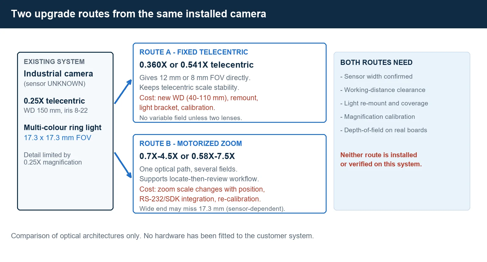
Figure 3 — The two routes and the prerequisites they share. Architectural comparison only; neither has been fitted.
The Coverage Matrix Depends on W, Not on the Zoom Ratio
This is the section that saves money. A 12.5:1 zoom ratio sounds strictly better than a 6.5:1 ratio, and it is — in range terms. But range is not coverage, and coverage at a specific field is decided by the effective image width W, which has nothing to do with how far the lens can zoom.
Put the three plausible values of W through the same arithmetic:
| Assumed effective width W | Magnification for 12 mm / 8 mm | What actually covers the target |
|---|---|---|
| 4.325 mm (derived from the existing lens) | 0.360X / 0.541X | 8 mm: 0.5X telecentric gives 8.65 mm, or a 0.5X–1.0X macro zoom tuned to 0.54X. 12 mm: no standard step — 0.3X gives 14.4 mm, 0.5X gives 8.65 mm. Custom or two-lens only. |
| 8.8 mm (if the full 2/3″ frame is used) | 0.733X / 1.100X | 0.58X–7.5X zoom covers both: 15.2 mm at 0.58X, 8.0 mm at 1.1X. But 17.3 mm would need 0.509X, below the wide end, so the wide view is lost. |
| 12.8 mm (if the full 1″ frame is used) | 1.067X / 1.600X | 0.68X–5.0X zoom covers all three: 18.8 mm at 0.68X, 17.3 mm at 0.74X, 12.0 mm at 1.07X, 8.0 mm at 1.60X. |
Read the middle row carefully, because it is counter-intuitive. The 12.5:1 lens has by far the largest ratio, and its wide end is 0.58X. On an 8.8 mm effective width, 0.58X produces a 15.2 mm field — which cannot show the 17.3 mm the machine sees today. A lens with a bigger zoom ratio than the current fixed lens still cannot reproduce the current wide view. Zoom ratio tells you how much the magnification can change; it does not tell you where the range starts.
Now state the requirement the honest way. To keep 17.3 mm and also reach 12 mm and 8 mm on the same camera, a single lens would need roughly a 0.25X to 0.55X range. Looking through the POMEAS catalogue, the closest shapes are a 0.5X–1.0X telecentric macro zoom at 75–106 mm working distance, which loses the wide end, and the 0.58X–7.5X zoom, whose wide end of 7.46 mm at a 4.325 mm width falls far short of 17.3 mm. There is no verified catalogue model that covers 17.3 mm, 12 mm and 8 mm at once. That is the honest answer, and it is worth more to a customer than an optimistic one.
There is a technical path that could shift the whole range downward: a variable zoom combined with a reducing attachment or a TV adapter placed between lens and camera. The direction is standard optics, but the specific magnification steps and the image-circle compatibility must be confirmed by POMEAS engineering for the actual lens and camera, so it is presented here as preliminary and not as a validated configuration.
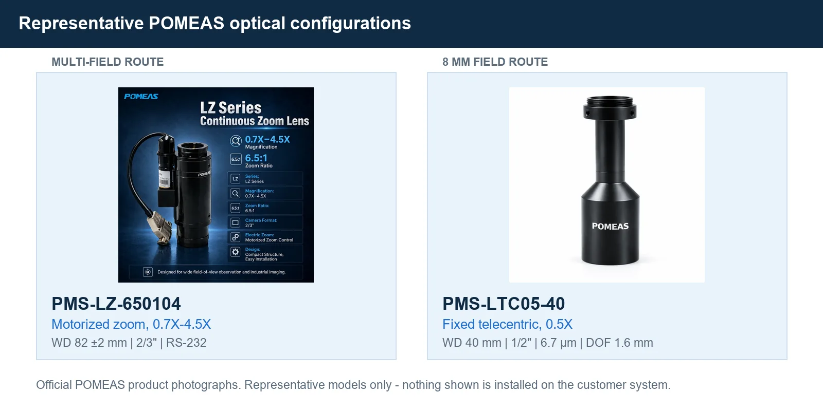
Figure 4 — Representative POMEAS configurations for the two routes. Official product photographs; nothing shown is installed on the customer's machine.
What Changes Mechanically, Optically and in the Lighting
The optical arithmetic is the easy half. The half that decides whether the project succeeds is what happens to the machine around the lens, and it starts with working distance.
Working distance collapses. The existing lens sits at 150 mm. The candidates sit at 40 mm (0.5X telecentric), 85 mm (1.0X), 110 mm (0.3X), 77.4 ± 2 mm (12.5X zoom) and 82 ± 2 mm (6.5X zoom). In round terms, the camera and lens assembly must move down by 40 to 110 mm. That is not a shim adjustment: the Z-axis travel must have the remaining stroke, the bellows or light shielding must still fit, and the frame must not foul the gantry at the bottom of its travel.
The ring light has to be redesigned, not just moved. The multi-colour ring light is bracketed under the lens with a hexagonal diffuser, and at 150 mm it produces a particular spot diameter on the board. Shorten the working distance to 40–110 mm and two things change at once: the illuminated spot shrinks, and the angle at which light reaches the board steepens. The practical outcomes are a darker periphery, glare off solder mask at grazing incidence, and cross-talk between colour channels that were previously distinguishable. None of this appears in a lens datasheet, and all of it shows up in the first image after installation.
The mount has to be checked against the barrel. A 6.5X zoom body is 119.9 mm long with a 44 mm outer diameter, and telecentric barrels are longer still. The existing clamp was sized for the 0.25X barrel. Re-clamping a longer, heavier assembly on the same bracket changes the moment load on the Z carriage, which is a vibration and repeatability issue rather than a cosmetic one.
Depth of field becomes the dominant risk. The existing lens can be stopped down to f/22, so it has aperture headroom to trade. The candidates are worse off: 4.4 mm depth of field at 0.3X, 1.6 mm at 0.5X, 1.00 mm at 1.0X, and progressively less as a zoom is pushed toward its long end. PCB assemblies have connectors, shields and electrolytic cans standing several millimetres proud of the substrate. At 1.00 mm depth of field, a board that focused acceptably at 0.25X will now show a mix of sharp and soft regions, and the operator will blame the lens when the answer is the height map. Stopping down recovers some depth of field at the cost of light and diffraction-limited sharpness, which is exactly the wrong trade at higher magnification.
Aperture and illumination have to be re-tuned together. Higher magnification concentrates the same light into a smaller area, so exposure usually improves while uniformity degrades. Plan on a lighting re-qualification pass with real boards, not a bench test with a calibration target.
Confirm These Before Anyone Buys a Lens
The list below is short, and every item on it is currently unknown. Each one can change the lens specification, so none of them should be filled in by assumption — not by us, and not by the customer's purchasing department.
- Camera model and effective image width W. The single most important value. Confirm from the datasheet, and confirm whether the AOI software crops a square ROI.
- Sensor format, resolution and pixel pitch. These convert the relative sampling improvement into an absolute micrometre-per-pixel figure.
- Lens mount and flange distance. Determines whether an adapter is needed and whether the candidates can physically mount.
- Light source model, channel count and driver. Needed to re-qualify illumination after the working distance changes.
- Z-axis remaining stroke and frame clearance. The assembly must descend 40–110 mm without fouling anything.
- Whether the AOI software can read back magnification and repeat calibration. A prerequisite for Route B, and a validation step for Route A.
- Smallest defect to be detected, and the measurement tolerance required. These decide whether the sampling improvement from 1.442× or 2.163× is sufficient, or whether the camera also has to change.
If you are still at the stage of choosing the machine rather than upgrading one, the PCB AOI optical selection guide covers that decision in the forward direction, starting from the defect size rather than from an installed lens.
Frequently Asked Questions
Can I keep my AOI camera and change only the lens?
Yes, if the new lens' image circle covers the sensor area the software uses, and if the mount and flange distance are compatible. The limiting factor is rarely the camera and almost always the mechanical envelope: the new lens will have a shorter working distance, a longer barrel, and a different light bracket requirement. Confirm the effective image width before ordering, because a lens chosen for the wrong width will miss the target field by a wide margin.
What magnification do I need for a 12 mm or 8 mm field of view?
It depends on the effective image width, not on the field alone. On the 4.325 mm effective width derived from this machine's 0.25X lens and 17.3 mm field, a 12 mm field needs 0.360X and an 8 mm field needs 0.541X. In relative terms those are 1.442 and 2.163 times the current magnification, which are ratios rather than orderable lens values. If the camera uses a larger sensor area, both absolute figures rise proportionally.
Will cropping the ROI in the AOI software give me more detail?
No. Cropping reduces the field of view and the pixel count across that field by the same factor, so the object size represented by one pixel is unchanged. You get a smaller window of the same image. More detail requires either higher optical magnification, which keeps the pixel count and shrinks the field, or a camera with smaller pixels, which keeps the field and raises the pixel count.
Why does a 12.5:1 zoom lens not automatically cover my 17.3 mm field of view?
Because zoom ratio describes the span of magnification, not where the span begins. A 0.58X to 7.5X lens has a 12.5:1 ratio, but at 0.58X on an 8.8 mm effective width it produces a 15.2 mm field, which is smaller than the 17.3 mm the machine sees today. Coverage of a specific field is decided by the effective image width and the required magnification, not by the ratio printed on the datasheet.
What happens to working distance and lighting when magnification goes up?
Working distance shortens, typically from 150 mm down to 40 to 110 mm for the candidate lenses, so the camera and lens assembly must be lowered and the Z-axis stroke re-checked. The ring light then sits closer to the board, which shrinks the illuminated spot, steepens the incidence angle and can introduce vignetting or cross-talk between colour channels. The light bracket and the illumination recipe both need to be re-qualified on real boards.
Conclusion: The Inspection Task Decides, Not the Lens Catalogue
Two conclusions survive the arithmetic. The first is that both routes are viable, and the choice between a fixed telecentric lens and a motorized zoom belongs to the inspection task: a single-pass inspection at one magnification favours the fixed lens, while a mixed product range with a coarse locate pass and a detail review pass favours the variable one. The second is that neither route can be specified until the effective image width is confirmed, because that single number moves the required magnification and changes which catalogue models qualify.
The workaround worth proposing regardless of route is a two-stage inspection: locate the board and the regions of interest at the wide field the machine already has, then switch to the narrow field only where detail is actually needed. That keeps the number of narrow-field images, and therefore cycle time, proportional to the defects being hunted rather than to the board area.
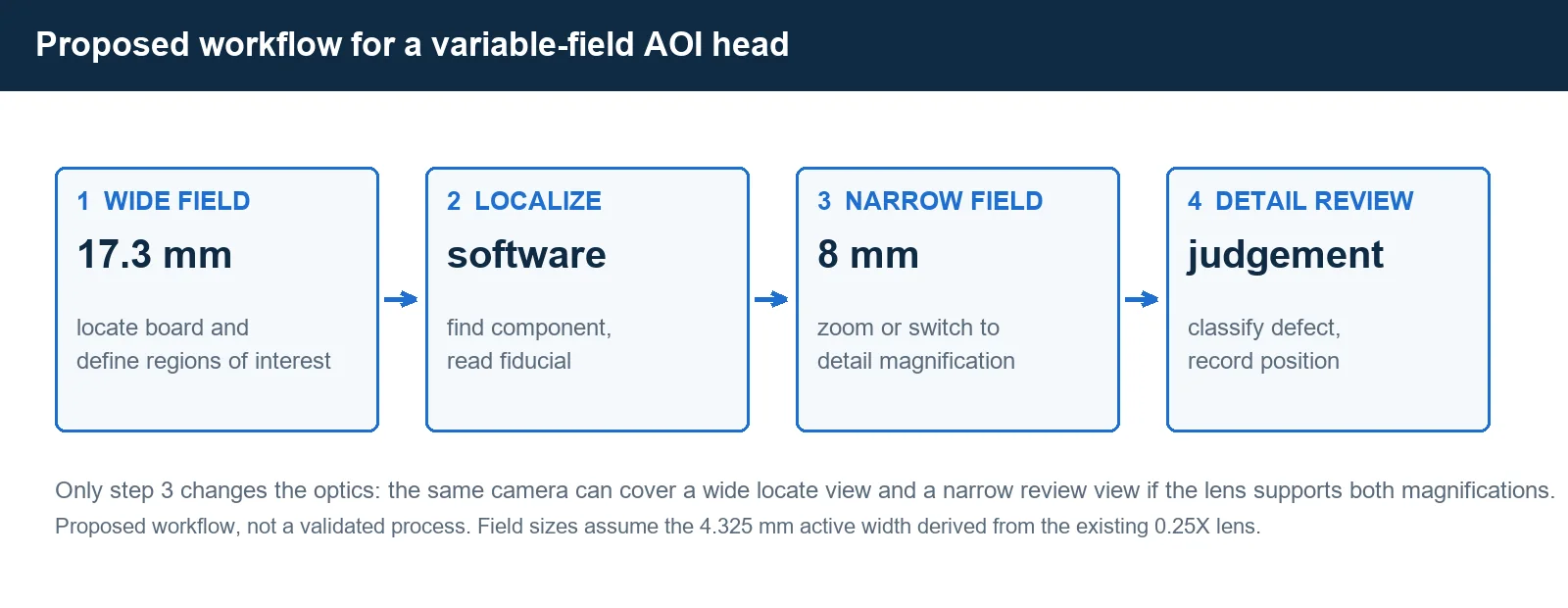
Figure 5 — Proposed two-stage workflow. Only the third step changes the optics; field sizes assume the derived 4.325 mm active width.
Send the camera datasheet, the current lens marking and the smallest defect you need to catch, and the magnification, working distance and light bracket can be specified against real numbers instead of assumptions. Contact POMEAS with those three items and the optical route can be narrowed to one recommendation.
Evidence note: the 0.25X magnification, the 150 mm working distance and the iris range are read from the customer's own photographs. All POMEAS specifications are from current product records. The 4.325 mm effective width, the 0.360X and 0.541X magnifications and the 1.442× and 2.163× ratios are derived and the arithmetic is shown in the text. Camera model, sensor format, pixel count, light source specification and the smallest defect size are unknown and remain to be confirmed. No hardware has been installed or tested on the customer's machine.

Subscribe to Our Newsletter
Simply enter your email to receive the latest news and insights from Pomeas. Stay connected with Pomeas and be the first to discover new innovations in optical excellence.


