知识库
How to Integrate a Motorized Zoom Lens into AI Vision Equipment
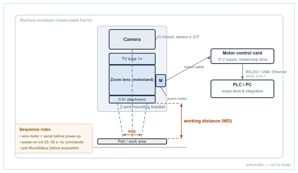
Integrating a motorized zoom lens into AI vision equipment is mostly a mechanical and controls exercise: the optics are only one decision among seven. This guide walks the full integration chain — camera and sensor, FOV and magnification, working distance, mechanical length, mount and centering, PLC/PC control, autofocus and equipment space — using the LZ-650104 6.5X motorized zoom lens as the worked example, because every number below comes from its official specification table, the POMEAS motorized lens user manual, and the official module mechanical drawing. Where a value depends on your specific build, it is marked [DATA REQUIRED].
Step 1 — Camera and sensor size
Start from the camera, because every downstream number is derived from it. The zoom lens projects a corrected image circle for a maximum sensor format; the LZ-650104 supports up to a 2/3-inch sensor on a C-mount camera. Using a larger sensor than the rated format crops nothing — it vignettes, so the corners of your AI training images will be dark.
Three camera-side facts you need before ordering:
- Sensor format and resolution — determines the image-side pixel size, and therefore the object-side sampling at each magnification.
- Mount — C-mount is the standard across the POMEAS motorized range.
- Exposure time — magnification changes do not move the part, so exposure requirements stay constant across the zoom range; this simplifies lighting more than most integrators expect.
Camera model and sensor resolution for your build: [DATA REQUIRED].
Step 2 — FOV and magnification
The governing relation is FOV = sensor dimension ÷ optical magnification. The LZ-650104 spans 0.7X–4.5X (6.5:1 zoom ratio), which on a 2/3-inch sensor gives the following official field-of-view table:
| Magnification | FOV diagonal | Resolution | Depth of field |
|---|---|---|---|
| 0.7X | 15.71 mm | 11.18 μm | 1.9 mm |
| 1.0X | 11.00 mm | — | — |
| 2.0X | 5.50 mm | — | — |
| 3.0X | 3.67 mm | 3.95 μm | — |
| 4.5X | 2.44 mm | 3.95 μm | 0.1 mm |
Two integration rules follow. First, verify the defect-budget check: divide your smallest feature by the sensor pixel size, then by magnification — if the defect lands on fewer than 3–5 pixels at the working magnification, no model will save it. Second, remember depth of field collapses as magnification rises (1.9 mm → 0.1 mm across this range), so Z-stage repeatability matters most at the top end. If the FOV/magnification terminology itself is fuzzy, the zoom vs magnification explainer clears it up.
Smallest feature or defect size for your application: [DATA REQUIRED].
Step 3 — Working distance: bare lens vs module
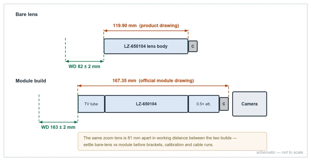
This is the most common integration mistake. The datasheet working distance describes the bare lens: the LZ-650104 focuses at 82 ± 2 mm from the lens front. The moment you add a 1× TV tube or a 0.5× attachment to reach a different WD/FOV envelope, the number changes completely. The official module drawing for the LZ-62010 TV tube + LZ-650104 + LZ-65605 0.5× attachment combination specifies:
- Module working distance: 163 ± 2 mm
- Module length: 167.35 mm
That is a 81 mm difference in working distance for the same zoom lens — nearly double. Decide the optical architecture (bare vs module) first, because it drives WD, envelope, and calibration together. The selection logic is worked through in the LZ-650104 machine integration selection case.
Step 4 — Mechanical length and equipment space
A motorized zoom lens is longer than it looks in product photos, because the motor section is part of the barrel. The LZ-650104 bare lens is 119.90 mm long; the module above is 167.35 mm — and that is before the camera body, the control card cabling, and service access for the connectors.
Practical envelope rules from completed integrations:
- Reserve length for the full stack: lens + TV tube/attachment + camera + connector clearance.
- Check the diameter at the motor section, not just the optical barrel — cable exits and the motor housing are the widest points.
- Verify the folded-path option early: when linear space runs out, a 45° fold mirror in front of the lens converts vertical clearance into horizontal (see the fold-mirror case study).
- Model the stack in CAD before machining brackets; verify with calipers on the first assembled unit.
Step 5 — Mount, parfocality and centering
The lens mounts to the camera on a standard C-mount (Ø25.4 mm thread). Two alignment procedures at installation determine optical quality for the life of the machine, and both are documented in the parfocality and centering SOP:
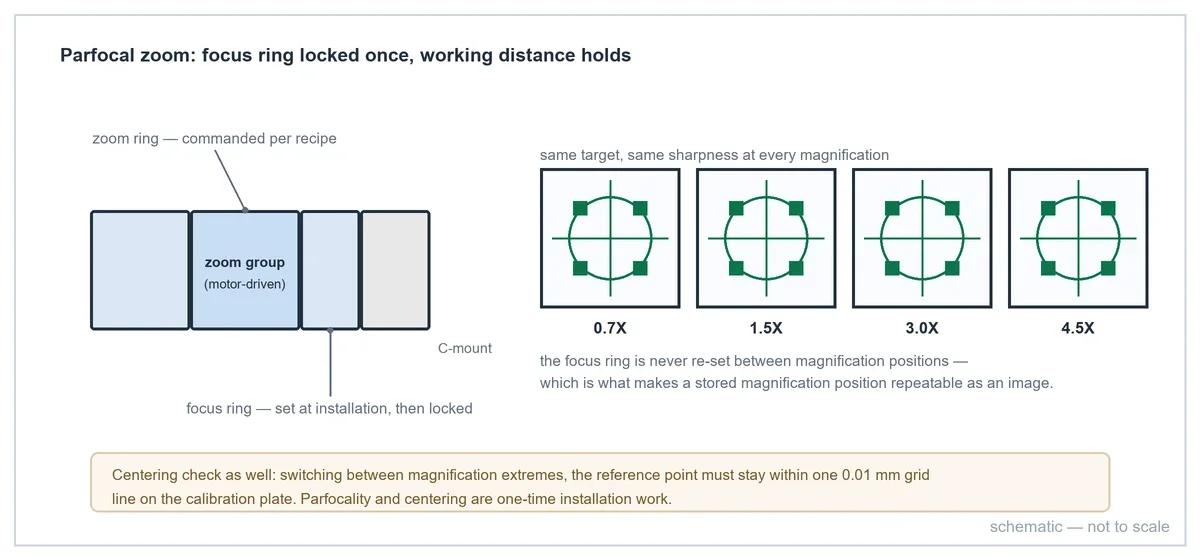
- Parfocality — adjust so the image stays sharp from minimum to maximum magnification. The procedure iterates max→min magnification one to two times, then locks the focus ring. On a parfocal model this is a one-time setup; the working distance then holds across the zoom range, which is exactly what recipe recall depends on.
- Centering — align the optical axis to the sensor center using the three C-mount screws, verified against a calibration plate: the reference point must stay within a 0.01 mm grid line when switching between magnification extremes. Skip this and your ROI maps drift between magnification positions.
Step 6 — Control: PLC, PC and the serial link
The control chain is: controller (PLC or PC) → control card → lens motor. The POMEAS control card takes a 12 V supply and connects to the lens motor with the dedicated motor cable; the controller side offers RS-232 serial or Ethernet on most models, with USB-to-serial as an option. Wiring order matters: connect motor cable and serial line before applying power.
The command interface is deliberately small, which is why a PLC-controlled zoom lens is a realistic pattern — no PC required for recipe recall:
open/close— port handlingMoveHome— return to mechanical originMoveGoto(pos)— drive to an absolute position (0 to total travel)MoveMaxLength()— read the total travel for the installed lensMovePos()/MoveStatus()— read current position and motion state (moving / idle / error)
Serial settings are fixed: 9600 baud, 8 data bits, no parity, no stop bits — the full frame format is in the RS-232 command protocol reference, and the dynamic-library calls for PC applications are in the SDK integration guide.
Three behaviors your machine program must handle:
- Power-on initialization: the lens runs an automatic initialization for 25–35 s after power-up and cannot be commanded during this window. Gate your startup sequence on status polling, not on a fixed timer at the low end of the range.
- Move completion: poll
MoveStatusuntil idle before triggering image acquisition — a fixed delay either wastes cycle time or grabs frames mid-move. - Cable runs: motor cables beyond 5 m must be the factory long-line version; do not splice or self-make motor cables.
PLC/PC split for your build (who stores recipes, who does setup): [DATA REQUIRED].
Step 7 — Autofocus: what the hardware gives you and what software closes
On parfocal models, autofocus is usually unnecessary: focus is fixed at installation and holds across the zoom range. Where part height varies, the dual-motor tier is the answer — the PMS-LZL-12110-Z12 adds a second, independently controllable axis (zoom + focus) over RS-232/USB. The lens does not focus itself; your vision software drives the focus axis, typically with a contrast- or sharpness-maximization loop over a few candidate positions, then locks the position into the recipe. For the trade-space against liquid lenses and other AF mechanisms, see the motorized autofocus FAQ.
Part-height variation across your product family: [DATA REQUIRED].
Integration checklist
| # | Item | Reference |
|---|---|---|
| 1 | Camera model, sensor format ≤ 2/3", C-mount | Camera datasheet |
| 2 | FOV/magnification plan: wide search + fine inspection positions | FOV table, this page |
| 3 | Optical architecture: bare lens (WD 82 ± 2 mm) or module (WD 163 ± 2 mm) | Product page + module drawing |
| 4 | Envelope: 119.90 mm bare / 167.35 mm module + camera + connectors | Mechanical drawing, CAD |
| 5 | Parfocality + centering performed and locked (≤ 0.01 mm) | Adjustment SOP |
| 6 | Control chain wired before power; 25–35 s init handled; status-polled moves | User manual, RS-232 reference |
| 7 | Focus strategy: fixed (parfocal) or vision-driven (dual-motor) | This page, Step 7 |
| 8 | Optical recipes stored as learned positions on the installed lens | Pulse position table |
Frequently asked questions
How long does it take to integrate a motorized zoom lens into an inspection machine?
The mechanical work is bracket machining plus parfocality/centering alignment; the controls work is wiring the card and adding position commands to the machine program. The one-time procedures — alignment, first recipe calibration — are measured in hours, not days, when the envelope has been verified in CAD beforehand.
Can the zoom lens be driven directly by a PLC?
Yes. The control card exposes a serial command set (RS-232 or Ethernet depending on model) covering position moves, homing and status polling, so a PLC can recall magnification positions as part of recipe execution. The fixed serial settings and command frames are documented in the RS-232 protocol reference.
What happens if we power-cycle the machine?
After every power-up the lens runs a 25–35 s self-initialization and rejects commands during that window. Your startup sequence should poll status until the lens is idle before issuing the first move.
Do we need to re-focus after every magnification change?
No — that is the point of parfocal design. Once parfocality is adjusted and locked at installation, the working distance holds across the zoom range. Only dual-motor setups with varying part heights use the focus axis dynamically.
What should we send the lens supplier before ordering?
Camera model and sensor size, required FOV range, working distance, smallest feature to resolve, available installation space, and the control environment (PLC model / PC OS). Those six inputs are enough to fix the lens model, the bare-vs-module decision and the control chain.
Need help integrating a motorized zoom lens into your AI vision equipment?
Send us:
- Camera model
- Sensor size
- Required FOV
- Working distance
- Smallest feature or defect
- Available installation space
- Control requirements
Related reading

邮件订阅
您将收到我们最新的动态资讯


