Knowledge
Integrating a Motorized Zoom Lens into an Automated Inspection Machine: Working Distance, Mechanical Length and Parfocality Verification
Application Note · Equipment Integration Series — This case note documents a real 2026 integration project in which a machine vision equipment builder fitted a POMEAS motorized zoom optical module into an automated inspection machine. Customer and machine details are anonymized. All numeric values below come from the project's own mechanical drawings, the CAD layout checks and POMEAS official product documentation.
1. The Integration Challenge
The customer builds automated vision inspection equipment. The machine under development had to inspect multiple product variants on one optical channel: different variants present different fields of view, and the inspection software needs to switch between an overview shot and magnified views of small features without stopping the line to swap lenses.
Three constraints made the optical selection difficult:
- One station, several fields of view. A fixed-magnification lens locks the FOV to one value. Every new SKU would have required either a different lens or a second camera station.
- Tight mechanical envelope. The optical axis was already fixed by the machine layout. The module — lens, relay optics, motor and mount — had to fit inside the existing Z-axis lifting stage without colliding with the frame, cabling or lighting.
- Software-driven optics. The vision software (and, downstream, the PLC) had to call specific magnification positions automatically, so the optics needed a defined electrical interface and repeatable positioning — not a hand-turned zoom ring.
2. Optical Requirements
| Item | Value / Status |
|---|---|
| Zoom lens family | POMEAS 630-series motorized zoom lens (project unit: LZ-63104; published sibling: LZG-63104-A) |
| Zoom ratio | 6.5X (confirmed, official product documentation) |
| Magnification range | 0.7X–4.5X (confirmed, official product documentation) |
| Working distance of zoom lens | 87 ± 2 mm (confirmed, official product documentation for the 63104 family) |
| Relay / tube optic | 1X mini TV tube lens (LZ-62010 family), added by the project BOM |
| Module mechanical drawing | Working distance 163 ± 2 mm, overall length 167.35 mm, C-mount, drawing units mm (values as printed on the manufacturer's mechanical drawing supplied for this project) |
| Camera mount | C-Mount (confirmed) |
| Control interface | POMEAS motor control card (encrypted, 512-motor type) + RS232 serial link; 12 V / 2 A supply (confirmed by project BOM) |
| Camera model / sensor size | Not fixed at the time of this record |
3. Why a Motorized Zoom Lens Was Used
A motorized zoom lens turns magnification into a software parameter. Instead of one fixed FOV per lens, the machine stores one zoom position per recipe:
- SKU A → pulse position A → FOV A (overview)
- SKU B → pulse position B → FOV B (detail)
- SKU C → pulse position C → FOV C (fine detail)
Changing product is a recipe switch, not a mechanical change. The zoom module keeps its working distance fixed while magnification changes, so the mechanical interface to the machine does not move — only the internal optics reposition. For an AI-vision workflow this is the foundation of adaptive FOV: the same camera can hand the algorithm both a context image and a magnified crop, on demand, in seconds.
4. Equipment Integration
The delivered kit (per the project BOM) covered the full control chain, not just the optics:
- Zoom lens: POMEAS LZ-63104 motorized zoom lens (630 series).
- Relay optic: 1X mini TV tube lens (LZ-62010 family) to adapt the optical path to the camera station.
- Drive: integrated motor unit below the lens barrel, driven by a POMEAS motor control card (encrypted, 512-motor type, housing included).
- Control link: RS232 serial cable between the machine's PC and the control card. The card also supports network control; serial and network are alternatives selected per machine architecture.
- Power: dedicated 12 V / 2 A adapter for the motor electronics.
- Optional wide-angle step: a 0.5X auxiliary lens, extending the low-magnification end of the system.
On the software side, the POMEAS control API exposes the operations an equipment PC or PLC layer needs: connect (serial or network), home the motor, move to an absolute pulse position, and query motion status. Serial communication runs at 9600 baud, 8 data bits, no parity. After power-up the lens motor performs an automatic initialization (typically 25–35 s) before accepting commands — the machine software must allow for this at every boot. Each magnification corresponds to a defined pulse position, so a "zoom preset" is simply a stored integer. The full mapping is published in the pulse position / magnification table, and the RS232 protocol and API reference plus the SDK integration guide describe the call sequence in detail.
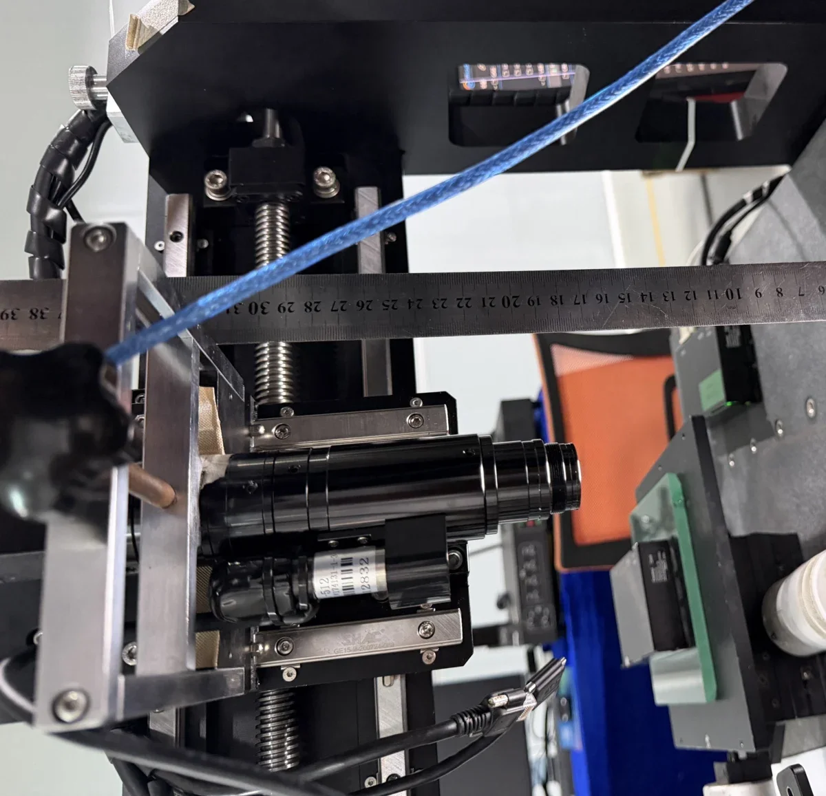
The motorized zoom module mounted on the machine's Z-axis lifting stage during commissioning. A steel rule was laid across the frame to verify clearances.
5. Engineering Issues Encountered
The interesting part of any integration is what nearly did not fit:
- Mechanical length vs. working distance. The module's mechanical drawing specifies a 163 ± 2 mm working distance and a 167.35 mm overall length. Both numbers must coexist inside the machine: the optical front must reach the object plane while the rear barrel, motor and cabling clear the frame. The project layout was therefore checked in CAD against the drawing before any bracket was machined.
- Envelope verification in CAD. Two distance measurements were taken on the integration model — 167.350 mm across the module (matching the drawing's overall length) and 204.350 mm along the optical path — confirming the layout absorbed the optics without redesign.
- Parfocality across the zoom range. A zoom lens must stay in focus from 0.7X to 4.5X. After the lens and tube were mounted, parfocality was adjusted using the manufacturer's procedure: focus at maximum magnification, loosen the focusing-ring and C-mount screws, rotate the focusing ring until the minimum-magnification image sharpens, and repeat across the range before locking. The parfocality and centering adjustment procedure documents the full steps.
- Optical centering. Because the sensor center and the optical axis rarely coincide perfectly, the C-mount's three screws were used to center the image across the zoom range, verified against a calibration plate with 0.01 mm grid lines.
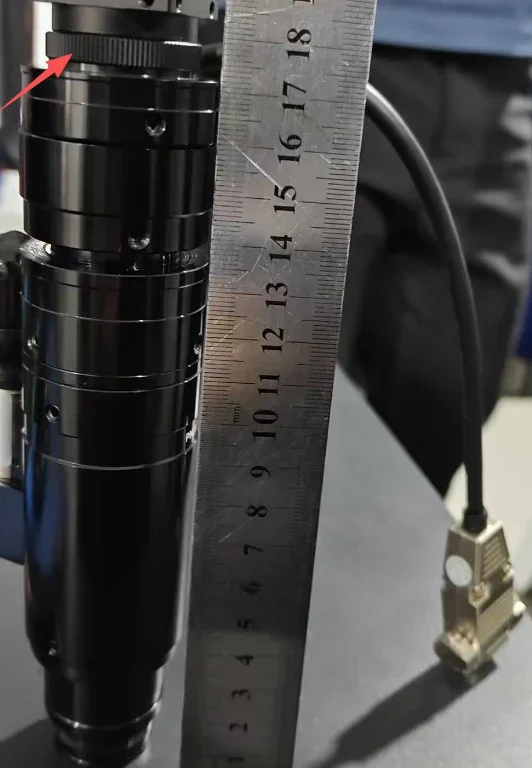
Parfocality adjustment in progress: the red arrow marks the focusing ring; the rule documents barrel position during the adjustment.
6. Solution / Adjustment
The final optical train — zoom lens, 1X tube, optional 0.5X auxiliary lens on C-mount, driven by the control card over RS232 — was mounted horizontally on an adjustable bracket inside the machine's Z-stage. On-site measurements with a steel rule and a digital caliper confirmed that the assembled module's envelope matched the CAD checks, and the parfocality/centering adjustments were performed on the machine, not on a bench, so the delivered state is the verified state.
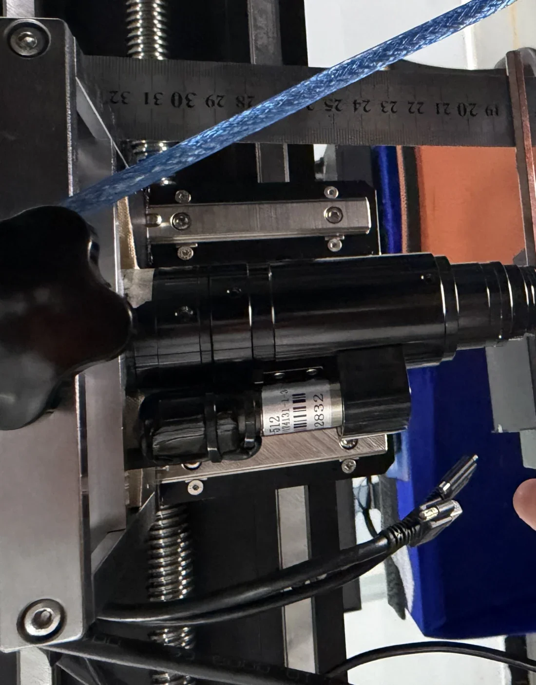
The zoom lens with its drive motor (labelled unit below the barrel) fixed to the machine bracket.
7. Verification
Verification performed and recorded during this integration:
- CAD distance checks of 167.350 mm (module length, matches drawing) and 204.350 mm (optical path) on the integration model.
- Physical measurement of the installed module with steel rule and caliper during on-site commissioning (photographed above).
- Parfocality and centering adjusted on the machine per the manufacturer's procedure, with image sharpness checked at both ends of the zoom range.
Quantitative inspection performance (accuracy, repeatability, cycle time) was not part of this integration record and is intentionally not claimed here. Physical sample verification was performed on-site before the machine's final release.
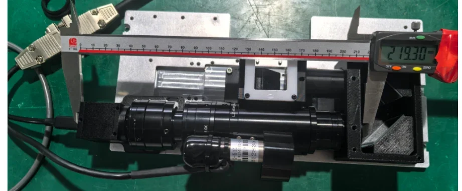
Bench verification of the assembled module: caliper and rule against the drawing's 167.35 mm overall length.
8. What This Means for AI Vision Equipment
This project is a small but complete example of programmable optics for automated inspection. Once magnification is a software value:
- one camera station serves multiple SKUs (multi-SKU inspection without hardware changes);
- the AI layer can request a context image and a magnified crop of the same part, enabling adaptive-FOV reasoning instead of fixed-FOV compromises;
- zoom presets stored as pulse positions are deterministic and repeatable, which is what recipe-based machine software requires;
- optics become part of the machine's control plan (PC / PLC / RS232), not a manually adjusted component.
For equipment builders, the selection question shifts from "what magnification do I need?" to "which magnifications must the software be able to call, and what envelope, interface and control chain do they demand?" General background: what a motorized zoom lens is and where motorized zoom lenses are used.
9. Integration Checklist
| # | Item to define before integration | Why it matters |
|---|---|---|
| 1 | Camera model and sensor size | Determines image circle and mount; this project left the camera open at BOM time |
| 2 | Required FOV set (min/max) per SKU | Maps to magnification range and zoom ratio |
| 3 | Working distance (optical) and available mechanical depth | Both must fit; WD 87 ± 2 mm (zoom) and 163 ± 2 mm module WD were the project's drawing values |
| 4 | Module overall length and diameter | Envelope check in CAD (167.35 mm here) before machining brackets |
| 5 | Camera mount (C/CS) and relay optics | Tube/auxiliary lenses adapt the optical path; parfocality depends on correct seating |
| 6 | Control interface (RS232 / network) and recipe design | Pulse positions per magnification; power-on initialization 25–35 s must be planned |
| 7 | Lighting layout | Coaxial or bar/flat lighting must clear the zoom barrel through the full travel |
Frequently Asked Questions
Why use a motorized zoom lens in automated inspection equipment?
Because magnification becomes a software parameter. One camera station can serve multiple product variants with different fields of view, switching by recipe instead of by physically changing lenses. This removes manual steps, keeps the working distance fixed, and lets inspection software combine overview and detail images of the same part.
Can a PLC or PC control a POMEAS motorized zoom lens?
Yes. The lens is driven by a POMEAS motor control card that connects to the machine's PC or control layer over RS232 (9600 baud, 8 data bits, no parity) or over a network link. The card's API provides connect, home, move-to-pulse-position and status-query operations, and each magnification corresponds to a stored pulse position, so machine recipes can call zoom presets directly.
How does a motorized zoom lens change the FOV of a machine vision system?
The motor repositions internal optics between defined pulse positions. Lower magnification gives a wider field of view; higher magnification gives a narrower, more detailed one — while the working distance stays fixed. The pulse-position-to-magnification mapping is documented per lens series, so each FOV is a repeatable integer value in software.
What is the difference between working distance and lens mechanical length?
Working distance is the optical distance from the lens front to the object plane (163 ± 2 mm on this project's module drawing). Mechanical length is the physical barrel dimension that must fit inside the machine (167.35 mm on the same drawing). Both must be verified: the optics must reach the object and the barrel, motor and cabling must clear the frame — which is why this project checked 167.350 mm and 204.350 mm distances in CAD before machining.
Does a motorized zoom lens stay in focus while zooming?
It is designed to be parfocal — focus is maintained across the zoom range — but after mounting lens, tube and camera, parfocality must be verified and trimmed: focus at maximum magnification, then adjust the focusing ring for the minimum magnification, repeating until both ends are sharp. Centering is trimmed with the C-mount screws against a 0.01 mm calibration grid.
Planning a motorized zoom integration?
Send POMEAS your camera model / sensor size, required FOV range, working distance, smallest feature to resolve, available mechanical envelope and control requirements — we will evaluate a suitable motorized zoom optical configuration for your machine. Contact POMEAS engineering, or start from the LZG-63104-A 6.5X motorized zoom lens or the 12.5X motorized zoom lens for higher zoom ratios. Optical performance verification methodology is covered in the POMEAS Technical Reference TR-001.
Companion case: LZ-650104 selection & integration case: WD 163mm module, RS232 control, pulse map

Subscribe to Our Newsletter
Simply enter your email to receive the latest news and insights from Pomeas. Stay connected with Pomeas and be the first to discover new innovations in optical excellence.


