Knowledge
Case Study: Fold-Mirror Integration of a Motorized Zoom Module in an AI Inspection Machine
When a builder of automated inspection equipment needed to fit a motorized zoom optical module into a machine whose viewing axis pointed straight down into a cramped work area, the linear stack — lens, tube, attachment, camera — simply did not fit. The solution was a 45° fold mirror in front of a POMEAS 65-series motorized zoom module, verified in CAD against the official module drawing and confirmed with calipers on the first assembled unit. This case walks through that integration using dimensioned schematics drawn for this page; every dimension quoted is either from the official POMEAS mechanical drawing or measured on the project's own parts. The customer is anonymous by agreement.
The application
The equipment is an automated inspection machine for small precision parts, using an AI vision routine: acquire a wide field, localize the region of interest, then drive magnification up for defect judgment. The optical requirements pointed to the 65-series motorized zoom module — the LZ-650104 6.5X zoom lens (0.7X–4.5X, 2/3-inch sensor, C-mount) combined with a 1× TV tube and a 0.5× attachment to reach the working distance the machine's geometry demanded.
The engineering problem: envelope, not optics
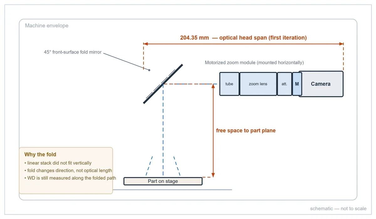
Optically, the module is a standard 65-series build. The constraint was space. The viewing axis points down into the work area, and the direct vertical stack could not be accommodated inside the machine's sheet-metal envelope. The machine builder's answer was architectural, not optical: turn the optical path 90° with a fold mirror, mount the zoom module horizontally on a bracket plate, and let the mirror do the bending.
The fold introduces its own integration burden: the mirror box becomes part of the optical path, the module mounts sideways (so the motor section must be reachable for cabling), and every millimeter of the stack has to be right before brackets are machined.
CAD verification against the official drawing
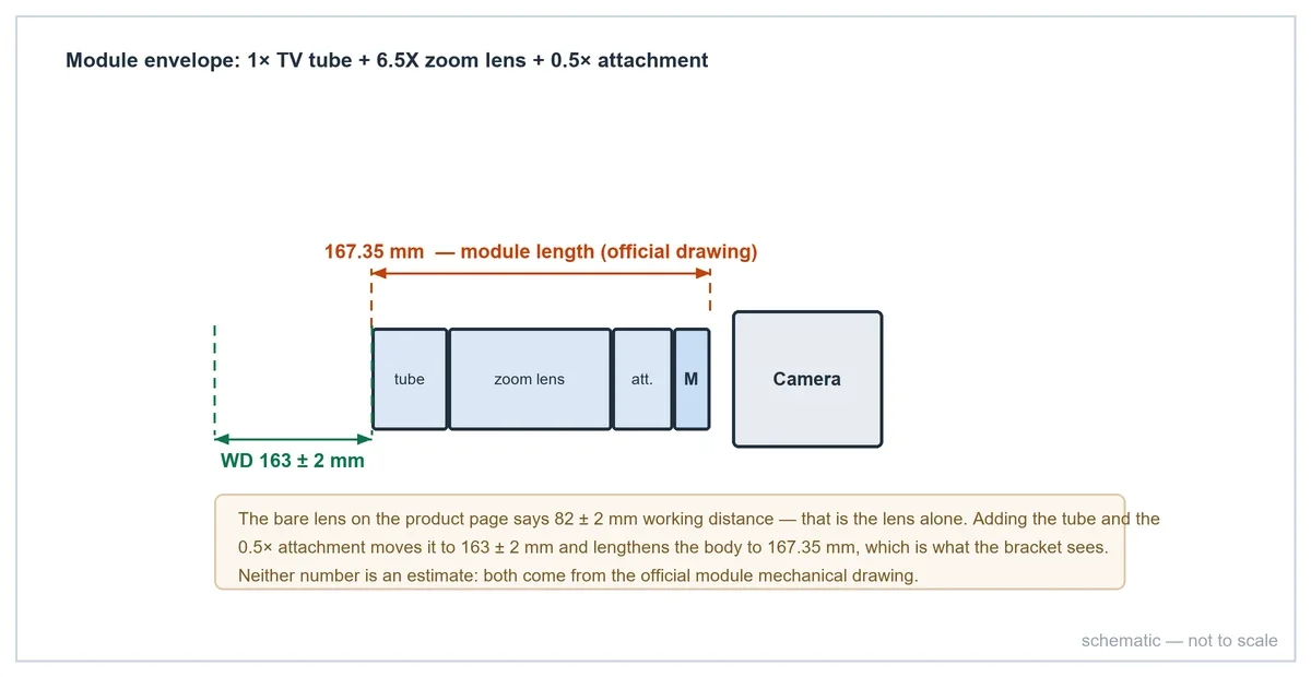
Two measurements from the project's CAD model frame the layout work. In the first iteration, the axial span across the optical head measures 204.35 mm. After the module layout was compacted, the span across the zoom module section measures 167.35 mm.
That second number is the significant one: the official POMEAS mechanical drawing for the LZ-62010 + LZ-650104 + LZ-65605 module combination specifies a module length of 167.35 mm and a module working distance of 163 ± 2 mm. The CAD measurement matches the drawing to the hundredth of a millimeter — which is exactly the point of verifying against the drawing rather than estimating from renders. Envelope claims that cannot be traced to a drawing do not survive contact with a machine frame.
As-built verification with calipers
On the first assembled unit, the builder verified the physical stack with a digital caliper before final installation. Two first-article checks record the spans: readings of 219.30 mm and 179.76 mm across the assembled optical head and bracket sections.
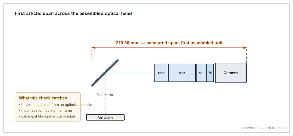
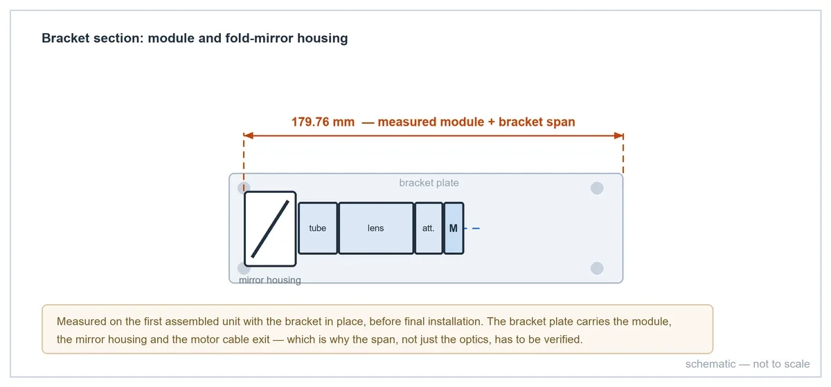
This is the verification step that prevents the classic integration failure — a bracket machined from an optimistic render, discovered wrong only when the lens physically will not seat. Measure the drawing, then measure the part.
Control chain
The module is driven by the standard POMEAS motorized-lens kit: a motor control card on a 12 V supply, the dedicated motor cable to the lens, and an RS-232 serial link to the machine controller (with Ethernet available as an alternative on the card). The control chain was laid out with the same discipline as the mechanics: the motor cable and serial line are connected before power is applied, and the machine program gates its startup on the lens's post-power initialization window — the lens runs an automatic initialization for 25–35 s after power-up and cannot be commanded during that time.
Magnification positions for the AI routine are stored as motor positions learned on the installed lens — wide-field search position and fine-inspection position — and recalled by the machine program with status polling between move and image acquisition. The command set and serial frame format are documented in the RS-232 protocol reference; the PC-side SDK calls are in the SDK integration guide.
What made the integration work
- Architecture before brackets: the bare-lens vs module decision (and its 82 mm working-distance consequence) was settled from the official drawing, not from datasheet assumptions about the bare lens.
- CAD traced to a drawing: the 167.35 mm module span in CAD was cross-checked against the official module drawing — a two-source match, not a single estimate.
- As-built measurement: caliper checks on the first assembly caught the real stack-up before final installation.
- Envelope solved optically: the fold mirror converted a vertical clearance problem into a horizontal one without touching the optical design.
- Control treated as a sequence: init window, polled moves, learned positions — the same discipline documented in the integration guide.
The same machine family, at earlier stages of this program, is documented in two companion cases: the 630-series equipment integration and parfocality verification case and the LZ-650104 selection case (bare lens vs module working distance).
Data notes: readings recorded during the project (CAD model and first-article measurement); module dimensions from the official POMEAS mechanical drawing for LZ-62010 + LZ-650104 + LZ-65605. Figures are dimensioned schematics drawn for this page — no customer drawings or photographs are published. Cycle times, camera model and part programs are customer confidential.
Frequently asked questions
Why use a fold mirror instead of a shorter optical module?
The fold mirror solves an envelope problem without changing the optics: the module mounts horizontally where linear space exists, while the viewing axis stays perpendicular to the part. It also keeps the module accessible for cabling and service.
Does the fold mirror affect image quality?
A front-surface mirror in the converging path adds no optical power; the integration requirements are mirror flatness, mounting stability and accurate 45° alignment during installation. The optical magnification range and resolution of the module are unchanged.
How do you verify the module will fit before machining brackets?
Two steps: model the full stack in CAD using the official mechanical drawing dimensions (module length 167.35 mm, working distance 163 ± 2 mm for the referenced combination), then verify the first physical assembly with calipers — as recorded in this case at 219.30 mm and 179.76 mm.
Which lens models support this kind of integration?
The 65-series motorized zoom lenses (0.7X–4.5X, 2/3-inch, C-mount) and 12.5X motorized models (0.58X–7.5X) integrate the same way; module configurations with TV tubes and attachments change working distance and length and must be taken from the corresponding official drawings.
What control hardware does the module need in the machine?
The standard kit: motor control card with 12 V supply, dedicated motor cable to the lens, and RS-232 serial (or Ethernet) to the machine controller. Startup must respect the 25–35 s initialization window, and magnification recipes are stored as positions learned on the installed lens.
Need help integrating a motorized zoom module into your equipment?
Send us:
- Camera model and sensor size
- Required FOV range
- Working distance
- Available installation space (or your CAD envelope)
- Smallest feature or defect to resolve
- Control requirements (PLC / PC)
Related reading

Subscribe to Our Newsletter
Simply enter your email to receive the latest news and insights from Pomeas. Stay connected with Pomeas and be the first to discover new innovations in optical excellence.


