Knowledge
PCB Repair Station Optics: Zoom Lens vs Stereo Microscope
A repair bench has different optical requirements from an inspection line, and the deciding factor is almost never magnification. Repair work needs room above the board for a soldering iron, hot-air nozzle or tweezers, a field wide enough to see a connector and its neighbour in the same view, and enough depth of field that a slightly bowed board stays in focus. A stereo microscope gives binocular depth perception at a fixed working distance; a C-mount zoom lens on an industrial camera gives a shared screen, a recorded image and a longer working distance, at the cost of stereo cues. Which one is right depends on four numbers, and this article works them out for a repair station rather than for an AOI machine.
What a repair bench actually asks the optics to do
Four tasks repeat all day at a rework station: locating a component on a dense board, reading its orientation and marking, judging a solder joint for bridging or insufficient fill, and verifying the result after rework. Each has a different field-of-view requirement. Locating a part on a 200 mm board needs a field of tens of millimetres. Reading a 0402 marking or a 0.4 mm pitch pin needs a field of a few millimetres. Judging a fillet needs resolution fine enough to see the concave meniscus, which in practice means a few micrometres per pixel. Verifying rework is the same as judging a joint, but it also benefits from a saved image, because a second person may need to agree.
The consequence is that a repair station needs a zoom range, not a single magnification, and it needs the range to change without the operator re-clamping the board. That is the same argument that makes zoom optics useful in machine vision, covered in zoom lens versus fixed focal lens for machine vision inspection, except that here the operator, not a motion controller, turns the ring.
Where a stereo microscope still wins
Stereo vision is not a marketing feature. Two offset optical paths give the operator genuine depth perception, and at a rework station that matters when a probe tip has to descend onto a 0.5 mm pad. Binocular viewing also keeps the operator's hands and eyes in the same physical space, which shortens the hand-eye loop during fine touch work. A stereo microscope with a 0.7× to 4.5× objective and 10× eyepieces delivers roughly 7× to 45× total visual magnification, and the working distance of that class of instrument is typically in the 90 mm to 100 mm range, which is enough to get an iron under the objective at an angle.
None of that is replaceable by software. A single camera looking down at a board produces a flat image, and no amount of display resolution restores the binocular cue. If the work involves guiding a tool by eye onto a small target, this is the dominant consideration.
Where a camera-based zoom lens wins
Three things change once the image goes to a screen. First, the working distance is set by the lens, not by the eyepiece geometry, and a C-mount zoom lens in the POMEAS 6.5× family is specified at 87 ± 2 mm, in the 12.5× family at 77.4 ± 2 mm and in the 14× family at 77.8 ± 2 mm. Second, several people can look at once, which matters for training, for a second opinion on a marginal joint, and for a supervisor signing off rework. Third, the image can be captured with the measurement or the defect marked, so the record exists after the board leaves the bench.
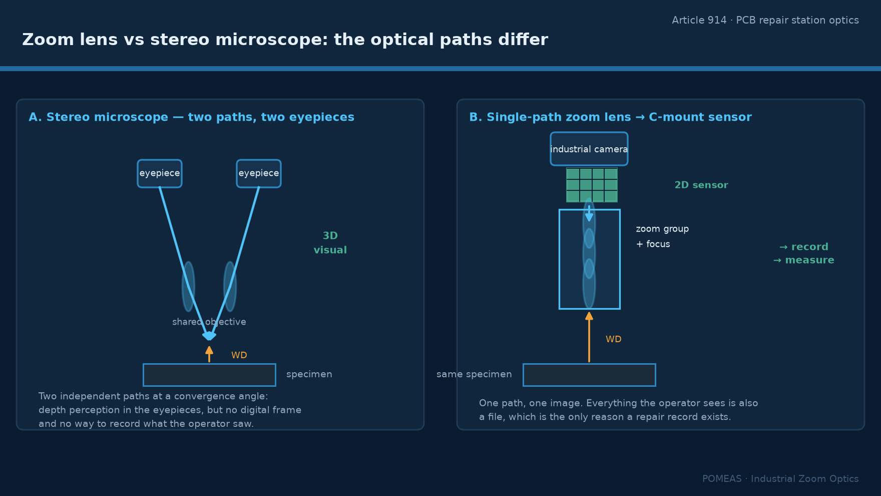
There is a fourth effect that is easy to underestimate: a screen at eye level lets the operator sit upright. Over an eight-hour shift that changes error rates more than a marginal gain in resolution does.
The working-distance constraint nobody budgets for
A hot-air nozzle needs clearance and approach angle. A lens at 77 mm working distance leaves room for a nozzle and a hand, but not for a nozzle approaching at 45 degrees while the operator also holds the board. This is where a short working distance becomes a real constraint rather than a specification. Two practical responses: choose the longer working distance in the family where a variant exists, or mount the lens on an articulated arm so it can be swung clear during heating and swung back for inspection.
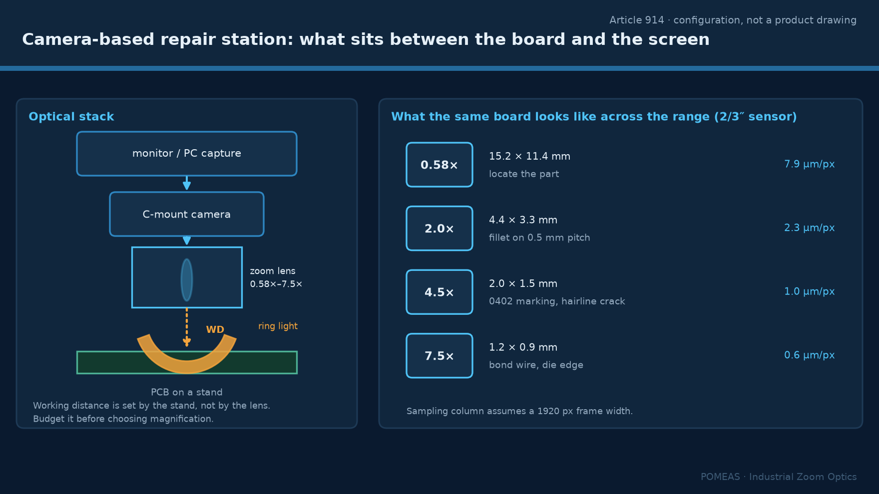
Working distance and field of view trade against each other in every optical design, and the real values across a product range are tabulated in zoom lens working distance: nine real WD values explained. For a repair bench, 80 mm is a workable minimum and 100 mm is comfortable.
Magnification arithmetic for a repair bench
Field of view is sensor width divided by optical magnification. With a 2/3-inch sensor, whose imaging area is 8.8 × 6.6 mm, the numbers below follow directly. They are geometry, not measurements, and they assume the lens is used at the magnification marked on its ring without extension tubes.
| Optical magnification | FOV on 2/3″ (H × V) | Sampling at 1920 px width | Typical repair task |
|---|---|---|---|
| 0.58× | 15.2 × 11.4 mm | 7.9 µm/px | Locating a part, viewing a connector row |
| 1.0× | 8.8 × 6.6 mm | 4.6 µm/px | Orientation, marking, coarse joint check |
| 2.0× | 4.4 × 3.3 mm | 2.3 µm/px | Fillet shape, bridging on 0.5 mm pitch |
| 4.5× | 2.0 × 1.5 mm | 1.0 µm/px | Fine-pitch pin, 0402 marking, hairline crack |
| 7.5× | 1.2 × 0.9 mm | 0.6 µm/px | Bond wire, die edge, micro-crack |
The 7.5× row is where the 12.5× family tops out with a 2/3-inch sensor. On a 1-inch sensor, a 4K zoom lens at 0.68× to 5.0× covers 18.8 × 14.1 mm down to 2.6 × 1.9 mm, which suits boards that are large but not fine-pitch. The two ranges are compared directly in 6.5× versus 12.5× industrial zoom lenses.
Depth of field and the bowed-board problem
Depth of field shrinks roughly with the square of magnification, so the magnification that resolves a fillet is also the magnification that cannot tolerate a board that is not flat. In the POMEAS 12.5× motorised series, published depth of field falls from 2.75 mm at 0.58× to 0.056 mm at 6.5×. That is a factor of about 49 across the zoom range, and it means a repair station that inspects at 6× needs either a board support that flattens the area under view or a focus adjustment with fine travel. This is why the 6.5× family includes variants with 3 mm and 12 mm fine-focus travel: the mechanism exists to absorb exactly this problem.
If depth of field is the binding constraint at your working magnification, the levers are aperture, magnification and working distance rather than sensor choice; the trade-offs are set out in how to improve depth of field in industrial zoom lenses.
Three configurations that cover most benches
Bench doing mainly through-hole and connector rework. A 6.5× manual zoom lens at 87 mm working distance on a 2/3-inch camera, with the 12 mm fine-focus variant if boards vary in thickness. The 0.7× end gives 12.6 mm of field, enough to see a connector and its silkscreen together, and 4.5× is enough to judge a fillet.
Bench doing fine-pitch SMD and BGA edge work. A 12.5× coaxial zoom lens at 77.4 mm working distance, which extends to 7.5× with 1.2 mm of field. Coaxial illumination matters here because it lifts solder wetting contrast on a shadowed joint. The manual variant is PMS-LZL-12101D.
Bench that also documents findings. The same optics with a capture workflow, plus a 14× lens if die-level features are in scope: the POMEAS 14× series reaches 2.80 µm optical resolution at 5× and above, with 1.26 × 0.95 mm of field on a 2/3-inch sensor at 7×.
What this setup does not solve
A camera-based zoom lens does not give stereo depth perception, so it is the wrong primary tool for guiding a probe or a blade by eye. It does not flatten a warped board, so it does not remove the need for fixturing. And it does not make a marginal joint measurable: judging wetting angle is still a visual judgement, and calling it a measurement would overstate what a 2D image can support. Where the task is genuinely dimensional, a telecentric system is the correct instrument, not a zoom lens.
Finally, magnification is not resolution. A 7.5× setting on a lens paired with a low-resolution camera produces a large, soft image, and the smallest feature actually visible is set by the optics and the sampling together, as set out in magnification is not resolution.
Frequently asked questions
Can a zoom lens replace a stereo microscope at a repair bench?
It can replace it for inspection, documentation and shared viewing, but not for tasks that depend on binocular depth perception such as guiding a probe by eye. Many benches end up with both: a stereo microscope for touch work and a camera-based zoom lens on an arm for inspection and recording.
What working distance do I need for hot-air rework?
Allow at least 80 mm between the lens front and the board if a nozzle has to approach at an angle, and prefer 100 mm where a variant exists. The POMEAS 6.5× family is specified at 87 ± 2 mm, which leaves room for a nozzle but not for a steep approach; an articulated mount solves the remaining problem.
Is 4.5× enough to read a 0402 marking?
On a 2/3-inch sensor at 4.5× the field is 2.0 × 1.5 mm and sampling is about 1 µm per pixel at 1920 px width, which is sufficient for most 0402 laser markings if illumination is controlled. If the marking is low contrast, raising magnification helps less than changing the illumination angle.
Why does the image go out of focus when I zoom in?
Most zoom lenses are parfocal only within a tolerance, and a lens that is not perfectly parfocal needs a small focus correction after a large magnification change. The adjustment procedure and the tolerance to expect are described in zoom lens parfocality and centring. A lens with a fine-focus ring makes the correction quick.
Do I need a motorised zoom for a repair bench?
Usually not. Motorised zoom earns its cost when magnification has to be changed by software, repeatably, inside a recipe. At a bench the operator changes magnification a few times per board, and a manual ring with a focus ring is faster to use than a jog interface.
What camera resolution makes sense at 7.5×?
Match sampling to optical resolution rather than maximising pixel count. At 7.5× on a 2/3-inch sensor, a 1920-pixel-wide camera samples about 0.6 µm per pixel, which is already finer than the 2.8 µm optical limit of a 14× class lens at high magnification; a higher pixel count adds file size without adding visible detail.

Subscribe to Our Newsletter
Simply enter your email to receive the latest news and insights from Pomeas. Stay connected with Pomeas and be the first to discover new innovations in optical excellence.


