Knowledge
How to Improve Depth of Field in Industrial Zoom Lenses: A Real Imaging Case
When a machine vision system is asked to inspect a part that is not perfectly flat, the first complaint is usually the same: “The center is sharp, but the edges or background are soft.” Engineers often blame the lens resolution, but the real limit is frequently depth of field (DOF) — the axial range in object space that appears acceptably sharp at one focus setting.
This article walks through a real POMEAS customer case. The customer started with one lens configuration and later moved to another, looking for a larger in-focus zone on a small precision part. We explain what actually changed, what did not, and how to make a similar decision without guessing.
Case at a glance
- Original configuration: POMEAS LZ-63100D6 detent zoom lens + LZ-62010A 1X MINI TV tube + LZ-66105 0.5X auxiliary lens
- Optimized configuration: POMEAS LZ-650100DS9 6.5X continuous zoom lens + 0.5X TV adapter + 1X auxiliary lens
- Test object: small four-terminal chip component
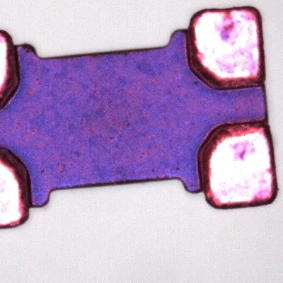
- Key outcome: the final image set shows a visibly wider in-focus zone (Case image 4)
1. Why Does the Background Become Blurry in Machine Vision?
Blur in a machine-vision image can come from three different sources. Treating them as one problem leads to the wrong fix.
1.1 Out-of-focus blur from shallow DOF
Every lens has a single object-plane that is perfectly focused. Away from that plane, the image becomes progressively softer. The distance between the nearest and farthest acceptably sharp object planes is the depth of field. If the part’s height variation exceeds the DOF, some regions will be blurry no matter how good the lens is.
1.2 Lens aberration or field curvature
A lens may focus the center and the edge of the field at different object distances. This is field curvature, not DOF. Stopping the aperture down will not fully correct it; the cure is a better optical design, proper alignment, or accepting a smaller region of interest.
1.3 Lighting, exposure, or reflections
Overexposed metal surfaces, glare, or low contrast can make details “disappear” even when they are in focus. In the sample images, the solderable terminals are bright and reflective; if the lighting angle or intensity is wrong, the edges look washed out rather than out of focus.
Take-away: before changing optics, confirm whether the blur is truly focus-related. A quick way is to refocus on the blurred region. If it becomes sharp while the previously sharp region blurs, the problem is DOF, not resolution.
2. How Does Aperture Affect Depth of Field?
In most imaging systems, a smaller aperture (larger f-number) gives a larger DOF, while a larger aperture gives a shallower DOF. This is because a smaller aperture reduces the cone angle of light rays from each object point, so the defocus blur circle grows more slowly on either side of the focal plane.
However, there are two practical limits:
- Exposure compensation: a smaller aperture passes less light. You need brighter illumination, a longer exposure, or higher camera gain to keep the same image brightness.
- Diffraction: at very small apertures, light spreads through the iris and the smallest resolvable feature becomes larger. The image gains DOF but loses fine detail.
For industrial inspection, the goal is therefore not “the smallest aperture possible.” It is the aperture that gives enough DOF while keeping the required resolution. The POMEAS 6.5X zoom lens family uses a manual or motorized iris so the aperture can be tuned for exactly this trade-off.
3. How Does Magnification Affect Depth of Field?
DOF shrinks as magnification increases. The reason is geometric: at higher magnification, the same physical distance along the optical axis maps to a larger distance on the image sensor, so it leaves the in-focus zone faster.
The POMEAS LZ-63100D6 6.5X detent zoom lens illustrates the relationship clearly. According to the POMEAS datasheet, at 0.7X the DOF is about 1.9 mm, while at 4.5X it drops to about 0.1 mm. A part with 0.5 mm of height variation may be fully in focus at 0.7X but only partially in focus at 4.5X.
| Optical magnification | Approx. DOF (mm) | Notes |
|---|---|---|
| 0.7X | ~1.9 | Lowest mag, largest DOF and FOV |
| 1.0X | ~0.95 | |
| 2.0X | ~0.29 | |
| 3.0X | ~0.16 | |
| 4.5X | ~0.10 | Highest mag, shallowest DOF |
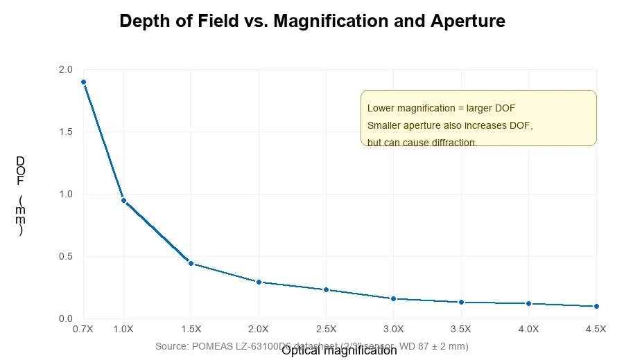
This is why a zoom lens is useful: when you need to see a large area, you use low magnification and gain DOF; when you need to see a tiny defect, you zoom in and accept a smaller DOF. If you need both at the same time, you must add Z-axis motion, autofocus, or multi-plane acquisition.
4. TV Adapter vs Auxiliary Lens: What Is the Difference?
The original and optimized configurations both include a TV adapter and an auxiliary lens, but the ratios were swapped. Understanding what each component does is essential before attributing any DOF change.
TV adapter (TV tube)
The TV adapter sits between the lens rear and the camera sensor. Its main jobs are:
- To project the intermediate image onto the camera sensor at the correct image distance.
- To set the system magnification seen by the sensor. A 0.5X TV adapter halves the sensor-side magnification compared with a 1X adapter.
- To match the lens exit pupil to the camera entrance pupil for uniform illumination.
Auxiliary lens
The auxiliary lens mounts on the object side of the zoom body. Its main jobs are:
- To change the object-side working distance and magnification of the whole system.
- A 0.5X auxiliary lens typically lowers magnification and increases WD; a 1X auxiliary lens preserves the base optical performance of the zoom body.
Configuration comparison
| Component | Original | Optimized | Optical effect |
|---|---|---|---|
| Main lens | LZ-63100D6 6.5X detent zoom lens | POMEAS LZ-650100DS9 6.5X continuous zoom lens | Different zoom body, possibly different NA and iris control |
| TV adapter | LZ-62010A 1X MINI TV | 0.5X TV adapter | Changes sensor-side magnification / image scale |
| Auxiliary lens | LZ-66105 0.5X | 1X | Changes object-side WD and base system magnification |
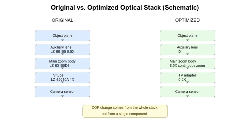
Because the main lens, TV adapter, and auxiliary lens all changed at the same time, the final DOF improvement cannot be credited to any single change. The 0.5X TV adapter does not “create” DOF; it changes the system magnification, which indirectly changes how much object height fits into the DOF. Likewise, switching from a 0.5X auxiliary lens to a 1X auxiliary lens changes the object-side magnification and working distance. The combined system must be evaluated as a whole.
5. Real Imaging Comparison: Before and After Optimization
The four images below were provided by the customer during the project. They show the same type of small four-terminal component under different optical setups.
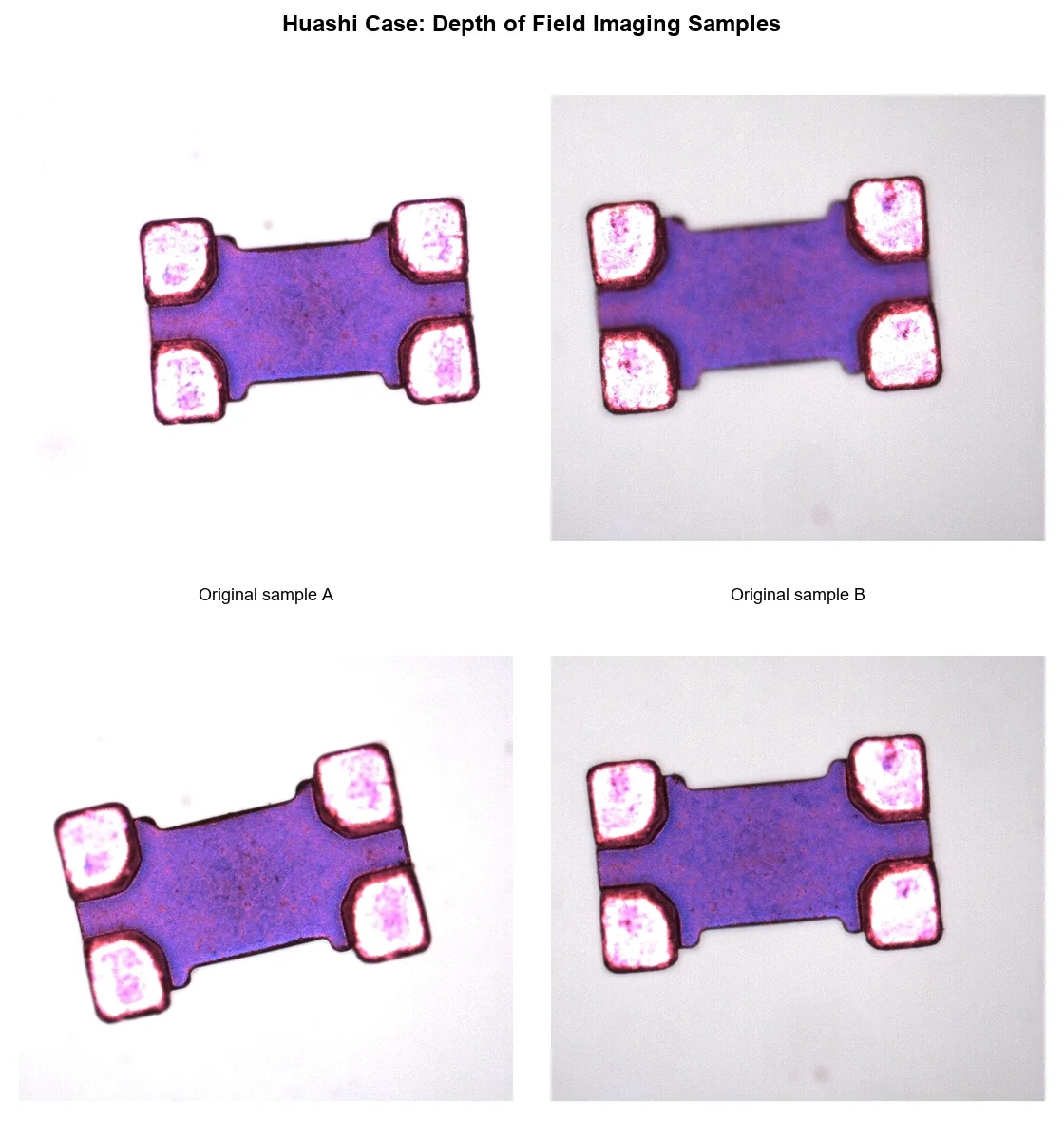
What we can observe:
- Images 1–3 show variations in focus and contrast. Terminals and body texture appear with different sharpness, suggesting the focal plane or magnification was not identical.
- Image 4 shows the whole component — body and all four terminals — in acceptable focus at the same time. The in-focus zone is visibly wider.
What we cannot claim:
- We do not have the exact magnification, aperture, or exposure settings for each shot, so these are not a controlled A/B test.
- The improvement in image 4 came from changing the entire optical configuration, not from a single knob such as aperture or TV adapter ratio.
6. How to Improve Depth of Field Without Sacrificing Image Quality
Use this decision flow when a part shows mixed sharpness:
- Measure the object height variation. The required DOF must be at least the part’s maximum height difference across the field.
- Check the actual field of view and camera pixel size. A smaller pixel pitch makes defocus more visible, so the usable DOF may be smaller than the optical DOF.
- Verify the focus plane. Make sure the focus is set on the most important feature, not on a random mid-height.
- Reduce magnification if the detail size allows. Lower magnification is the fastest way to gain DOF, but it also lowers the image scale.
- Stop down the aperture moderately. Increase the f-number until you reach the DOF target, then stop. Going further hits diffraction.
- Compensate exposure with lighting. Use a brighter coaxial, ring, or bar light so the aperture can stay small without raising camera gain.
- Re-evaluate the TV adapter / auxiliary lens pair. A lower TV ratio or a different auxiliary lens can change the system magnification and working distance.
- If the above is not enough, change the optical strategy. Consider a telecentric lens for constant magnification over depth, a Z-axis autofocus module for multi-height scanning, or multi-focus stacking.
Important: adding more light does not change the optical DOF. It only lets you stop the aperture down further without noise. True DOF is governed by magnification, aperture, and the acceptable blur criterion.
7. How to Choose the Right Zoom Lens
For a part similar to the one in this case, collect the following parameters before selecting the lens:
- Camera sensor size and pixel size
- Required field of view (FOV)
- Smallest defect or feature size
- Working distance constraint
- Object height variation (the required DOF)
- Required inspection speed / maximum exposure time
For 6.5X inspection of small electronic parts, the POMEAS LZ-650100DS9 6.5X continuous zoom lens covers 0.7X–4.5X with WD around 87 mm. For larger parts or more WD flexibility, the 12.5X continuous zoom lens provides a wider magnification range. For fully automated stations, the motorized 6.5X zoom lens with fine focus lets you set zoom and focus positions from software.
If the part has steep height changes and a large FOV, a telecentric lens may be a better long-term solution than pushing a zoom lens to its DOF limit.
8. Frequently Asked Questions
Does a smaller aperture always increase depth of field?
Yes, up to the diffraction limit. After a certain f-number, diffraction softens fine detail, so the effective resolution drops. The best aperture is the one that meets your DOF target without losing the smallest feature you need to see.
Does a 0.5X TV adapter increase depth of field?
Not directly. A 0.5X TV adapter reduces the sensor-side magnification, which can make the final image scale smaller. If the object-side optics stay the same, the same physical DOF is spread over fewer sensor pixels, so the apparent DOF may look larger. But the object-space DOF itself does not increase; it is a magnification effect.
Why does depth of field decrease at high magnification?
At higher magnification, the same physical distance along the optical axis maps to a larger distance on the sensor, so it leaves the in-focus zone faster. For example, the POMEAS LZ-63100D6 DOF drops from about 1.9 mm at 0.7X to about 0.1 mm at 4.5X.
Can a zoom lens inspect objects with different heights?
It depends on the height variation and the magnification. At low magnification, the DOF is larger and multi-height parts are easier. At high magnification, only a thin slice is in focus; you may need autofocus or Z-axis motion.
Does brighter lighting improve depth of field?
Brighter lighting lets you use a smaller aperture without raising exposure time or gain. The lighting itself does not change the optical DOF; it enables the aperture adjustment that does.
What is the difference between depth of field and image sharpness?
Depth of field is the axial range that is acceptably sharp at one focus setting. Image sharpness is the contrast of fine detail in the in-focus plane. A lens can be sharp but have shallow DOF, or have large DOF but mediocre sharpness.
When should I use autofocus instead of aperture adjustment?
Use autofocus when the part height varies between inspections or between positions in the FOV, and you cannot tolerate the resolution loss from a very small aperture. A motorized Z-axis or autofocus microscope captures the best focal plane at each point instead of trying to fit everything into one DOF.
9. Bottom Line
Depth of field in an industrial zoom lens is not controlled by one parameter. It is the result of magnification, aperture, the TV adapter ratio, the auxiliary lens, the camera pixel size, and the acceptable blur criterion. In the customer case, moving from the original configuration to a POMEAS LZ-650100DS9 6.5X continuous zoom system with a matched 0.5X TV and 1X auxiliary lens produced a visibly wider in-focus zone. The improvement came from the full optical stack, not from a single adjustment.
Before you buy or change a lens, measure the part height variation and the required feature size, then choose the lowest magnification and aperture that still resolve the target. If the geometry is too demanding, complement the zoom lens with autofocus, Z-axis motion, or a telecentric design.
Related reading: Parts With Different Heights: Depth of Field FAQ, 6.5X Zoom Lens Selection Guide, Zoom Lens Magnification and FOV Calculator.

Subscribe to Our Newsletter
Simply enter your email to receive the latest news and insights from Pomeas. Stay connected with Pomeas and be the first to discover new innovations in optical excellence.


