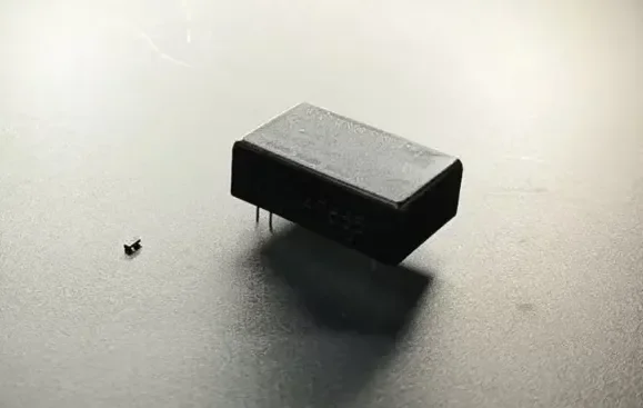
Application summary: A customer needed one machine vision lens to inspect chips ranging from 3 × 2 × 1 mm to 30 × 20 × 12 mm. The system had to capture clear printed characters and package markings for reliable OCR while continuously adjusting the short-side field of view from 50 mm down to 10 mm. A fixed-focal-length FA lens could produce a recognizable image, but the smaller chips occupied too few pixels, resulting in inconsistent character quality.
POMEAS evaluated an LZH-7504 motorized continuous zoom lens with a 1× tube lens and a 0.25× objective. The resulting optical magnification range of 0.17×–1.25× covers the required field-of-view range without changing lenses.
Inspection Requirements
The customer had to inspect multiple chip package sizes on the same system. The main requirements were:
- Minimum workpiece size: 3 × 2 × 1 mm
- Maximum workpiece size: 30 × 20 × 12 mm
- Target camera: Basler acA2500-20gc
- Inspection task: OCR recognition of printed characters and package markings
- Required short-side FOV: continuously adjustable from 50 mm to 10 mm
- Key image-quality requirement: sharp character strokes, strong marking contrast, and stable OCR output
The large variation in package size made a single fixed FOV impractical. A wide FOV was required to accommodate the 30 × 20 mm package, while a much smaller FOV was needed to enlarge the 3 × 2 mm package and allocate enough camera pixels to its printed characters.
Why the Previous FA Lens Produced Unstable OCR Images
The customer had previously tested FA lenses rated for 5 MP and 25 MP. The characters could be recognized under some conditions, but the chip occupied only a small area of the image. This reduced the number of pixels available for each character and made OCR performance sensitive to focus, illumination, noise, and part-position variation.
A higher megapixel lens rating does not automatically make a small target appear larger on the sensor. The object size in the image is primarily determined by optical magnification and FOV. Even a high-resolution FA lens cannot provide stable OCR if the selected FOV leaves the characters too small in pixel terms.
For OCR applications, the optical system must provide:
- Sufficient object-side magnification
- Enough pixels across the character height and stroke width
- Stable focus over the relevant package height
- High contrast between the marking and the chip surface
- Repeatable FOV and focus settings for each product recipe
Target Camera: Basler acA2500-20gc
The target industrial camera is a Basler acA2500-20gc color area-scan camera. Its 1-inch sensor format is an important selection factor because the lens must cover the full active sensor area without unacceptable vignetting or edge-performance loss.
| Camera Parameter | Specification | Relevance to This Application |
|---|---|---|
| Camera Model | Basler acA2500-20gc | Target camera selected by the customer |
| Sensor | onsemi PYTHON 5000, global shutter CMOS | Supports stable image capture of stationary or moving parts |
| Resolution | 2592 × 2048 pixels, 5 MP | Determines the available pixel count for character imaging |
| Active Sensor Size | Approx. 12.44 × 9.83 mm | Used to estimate the actual FOV at each magnification |
| Pixel Size | 4.8 × 4.8 μm | Used to calculate object-space sampling |
| Lens Mount | C-mount | Compatible with the proposed optical configuration |
Proposed Motorized Zoom Lens Configuration
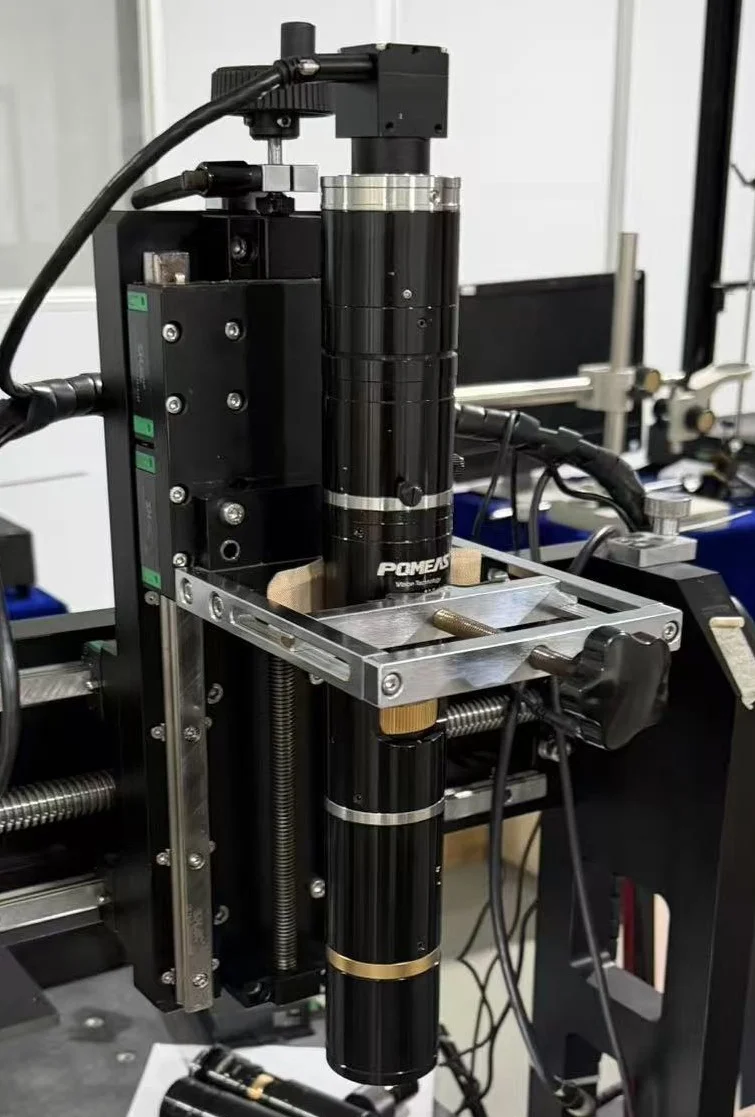
The proposed solution uses the following optical configuration:
| Component or Parameter | Selected Configuration |
|---|---|
| Zoom Lens | POMEAS LZH-7504 motorized continuous zoom lens |
| Mount | C-mount |
| Tube Lens | 1× |
| Objective | 0.25× |
| Overall Optical Magnification | 0.17×–1.25× |
| Nominal Theoretical FOV | 75.3 × 56.5 mm to 10.2 × 7.7 mm |
| Numerical Aperture (NA) | 0.0083–0.03 |
| Theoretical Object-Side Optical Resolution | 40.67–11.18 μm |
The nominal lens data shows that the system covers a short-side FOV from 56.5 mm down to 7.7 mm. The customer’s required 50–10 mm range therefore lies within the available continuous zoom range.
Because FOV depends on the camera’s actual active sensor dimensions, the expected full-sensor FOV with the Basler camera is approximately 73.2 × 57.8 mm at 0.17× and 10.0 × 7.9 mm at 1.25×. Small differences from nominal catalog values are normal and should be confirmed by calibration on the final system.
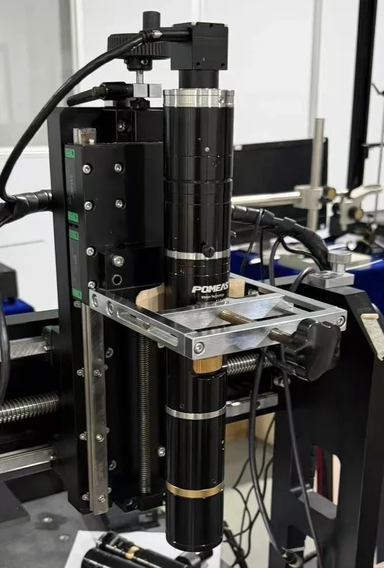
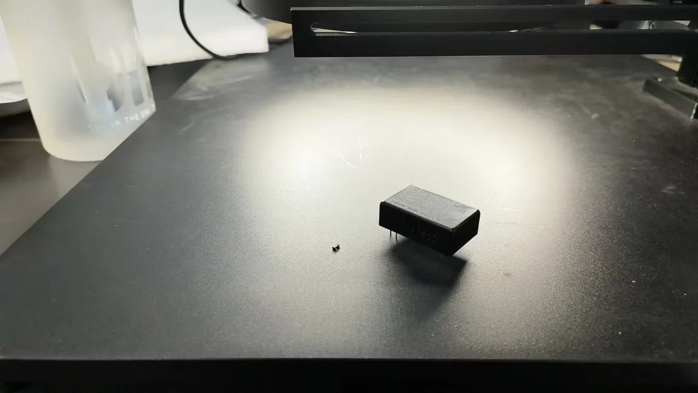
Real bench setup of the motorized zoom lens used for this chip OCR test.
How the Lens Covers the Required 50–10 mm Short-Side FOV
For a zoom lens, the object-side FOV can be estimated from the effective sensor dimension and optical magnification:
Object-Side FOV = Effective Sensor Size ÷ Optical Magnification
Using the Basler camera’s active sensor height of approximately 9.83 mm:
- For a 50 mm short-side FOV, the required magnification is approximately 0.197×.
- For a 10 mm short-side FOV, the required magnification is approximately 0.983×.
Both magnification settings fall comfortably inside the available 0.17×–1.25× range. This allows the lens to move continuously between the wide and narrow FOV settings without replacing optical components.
| Operating Point | Approx. FOV with Basler Camera | Approx. Object-Space Sampling | Expected Part Coverage |
|---|---|---|---|
| Wide FOV | 63.3 × 50 mm | 24.4 μm/pixel | A 30 × 20 mm chip occupies approximately 1228 × 819 pixels |
| Narrow FOV | 12.7 × 10 mm | 4.88 μm/pixel | A 3 × 2 mm chip occupies approximately 614 × 410 pixels |
These calculations explain why the motorized zoom configuration is more stable for OCR than a fixed wide-FOV setup. At the narrow setting, even the smallest chip occupies a meaningful portion of the sensor, giving the OCR algorithm substantially more character pixels.
The figures above assume that the 30 × 20 mm and 3 × 2 mm package dimensions are aligned with the camera’s long and short sensor axes. Actual pixel coverage will vary with part rotation, ROI settings, and the final calibrated FOV.
Optical Resolution Is Not the Same as μm per Pixel
The theoretical object-side optical resolution of 40.67–11.18 μm is derived from the lens NA and represents the optical system’s estimated ability to separate fine detail. Object-space sampling, expressed in μm/pixel, is determined by camera pixel size and magnification.
These two values should not be treated as interchangeable:
- Optical resolution describes how much detail the lens can transfer.
- Object-space sampling describes how much object distance is represented by one pixel.
- OCR reliability also depends on character height, stroke width, contrast, focus, illumination, noise, and the OCR algorithm.
At the required 50–10 mm short-side FOV, the Basler camera provides approximately 24.4–4.88 μm/pixel. Final OCR capability must still be verified using the smallest printed character and the actual production surface.
Why Motorized Continuous Zoom Is Better for Multiple Chip Sizes
A motorized continuous zoom lens provides several practical advantages for this application:
- One optical system covers multiple package sizes. The production line does not need to exchange fixed-focal-length lenses when the product changes.
- The FOV can be matched to each chip. Small packages can be enlarged for OCR, while large packages can be captured with sufficient positioning margin.
- More sensor pixels are used effectively. The character area occupies a larger percentage of the image, improving edge definition and OCR stability.
- Zoom positions can be integrated into product recipes. The control system can recall magnification settings for different chip models.
- Remote adjustment supports automation. Operators do not need to manually adjust the optical magnification during model changeover.
For repeatable production use, each stored zoom position should be paired with verified focus, exposure, illumination, and calibration settings. If dimensional measurement is also required, calibration should be performed at every operating magnification.
For a broader overview of zoom principles, automation benefits, and common industrial uses, see the application of zoom lenses in machine vision.
Imaging Test and OCR Result
POMEAS did not have the customer’s exact 5 MP, 1-inch camera available during the initial sample test. The imaging validation was therefore performed using a POMEAS 5 MP camera with a 2/3-inch sensor, combined with the LZH-7504 lens, 1× tube lens, and 0.25× objective.
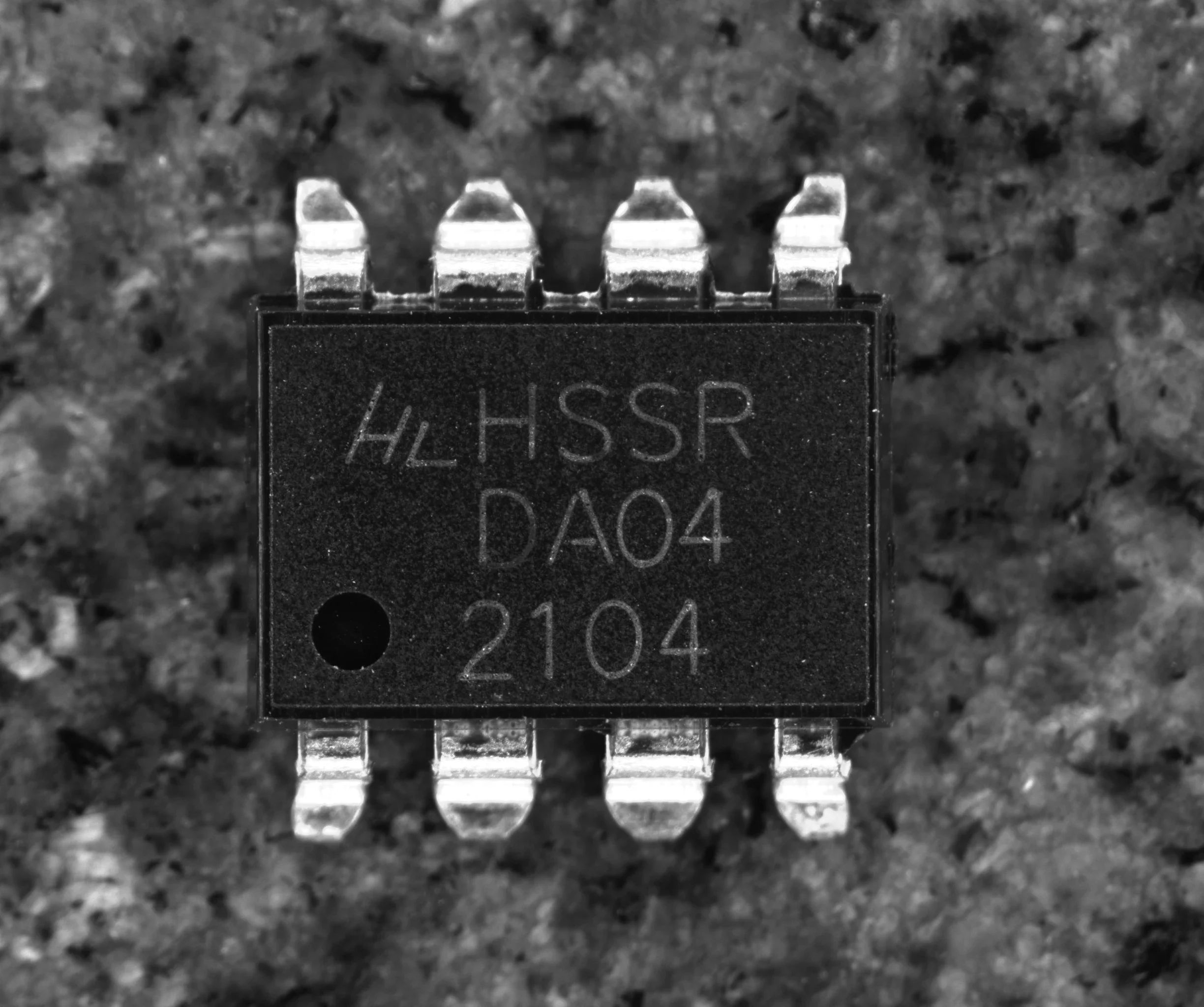
The sample images confirmed that the lens could reproduce the chip markings with clear character edges and sufficient contrast for OCR evaluation. Compared with the previous FA-lens image, the zoom lens allowed the chip to occupy a larger portion of the frame, improving the visibility of printed text and silkscreen details. A related POMEAS case also demonstrates how a 4K zoom lens supports chip appearance inspection.
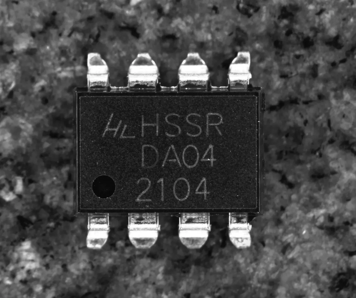
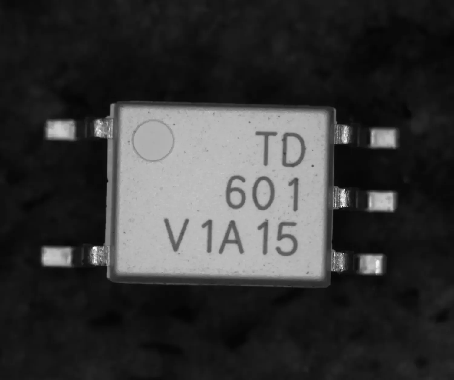
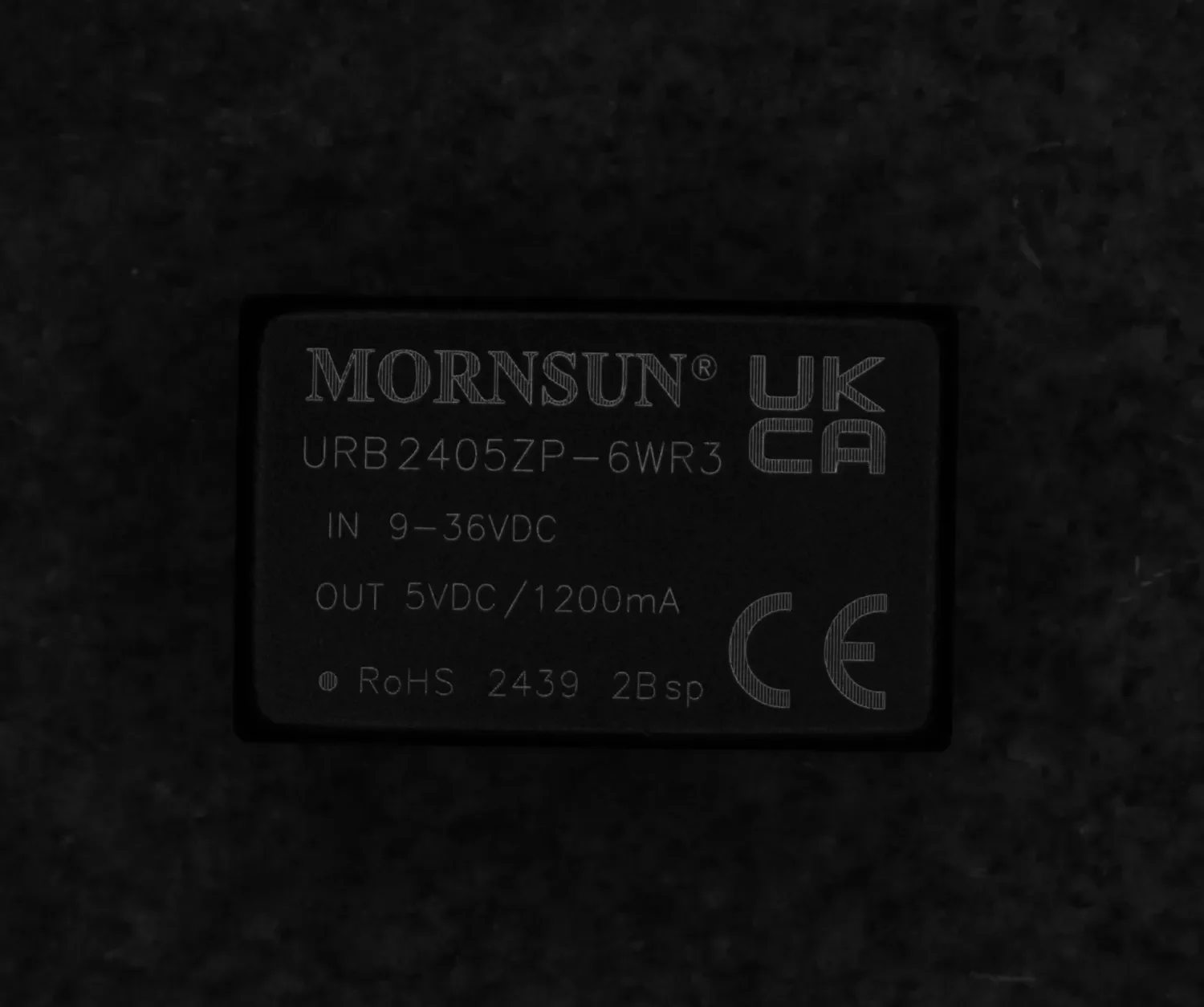
The 2/3-inch test camera validates the optical imaging quality of the proposed lens configuration. However, its FOV is smaller than that of the customer’s 1-inch Basler camera at the same magnification. The final FOV, focus, illumination, and OCR confidence should therefore be verified again after integration with the Basler acA2500-20gc.
Low magnification: the whole working area in one field for fast positioning.
Mid magnification: the chip is centered and the marking area fills the field.
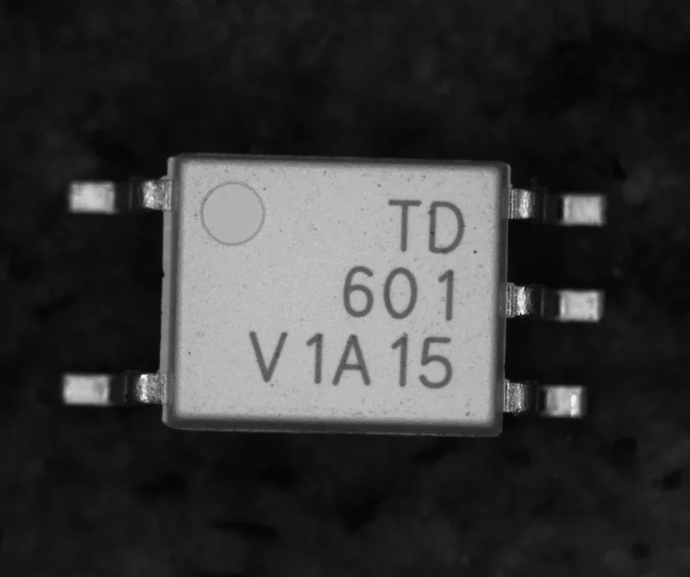
High magnification: the marked characters stay sharp for stable OCR.
Illumination Considerations for Chip Marking OCR
Magnification alone cannot guarantee stable OCR. Chip packages may have matte, glossy, molded, laser-marked, or printed surfaces, and each surface responds differently to machine vision illumination.
During final integration, consider the following:
- Use diffuse illumination to suppress local glare on reflective packages.
- Evaluate coaxial illumination for flat surfaces with low-contrast markings.
- Adjust the incident angle to enhance shallow laser markings or embossed characters.
- Keep exposure and light intensity stable across all zoom recipes.
- Verify the smallest character stroke, not only the overall chip outline.
The best illumination is the one that produces a stable grayscale difference between characters and the package surface across the entire production tolerance range.
Recommended Final Validation
Before releasing the system for production, the following checks are recommended:
- Confirm the actual FOV at both the 50 mm and 10 mm short-side settings.
- Verify full 1-inch sensor coverage and inspect corner sharpness.
- Measure the pixel height and stroke width of the smallest characters.
- Test all chip colors, marking methods, and surface finishes.
- Verify focus repeatability after repeated motorized zoom cycles.
- Store zoom, focus, exposure, illumination, and OCR parameters as product recipes.
- Evaluate OCR confidence under normal part-position, height, and orientation variation.
Conclusion
This case demonstrates that the main limitation of the previous FA-lens solution was not simply lens megapixel rating. The larger problem was that a fixed FOV could not allocate enough pixels to both the smallest and largest chip packages.
The LZH-7504 motorized continuous zoom lens, configured with a 1× tube lens and 0.25× objective, provides an overall magnification range of 0.17×–1.25×. Its available FOV range covers the customer’s required continuous short-side adjustment from 50 mm to 10 mm, while improving image scale and character visibility for chip OCR.
For a final lens recommendation, provide the minimum character height and stroke width, required OCR confidence, working distance, package reflectivity, line speed, available illumination space, and all required FOV settings. Sample testing with the production camera remains the most reliable way to confirm OCR performance.
Frequently Asked Questions
Why not use a higher-megapixel fixed FA lens for this chip OCR application?
A higher lens resolution rating may improve image detail, but it does not change how large the chip appears on the sensor. If the FOV is too wide, the chip and its characters still occupy too few pixels. A zoom lens changes the optical magnification so that each package size uses the camera resolution more effectively.
Is a 5 MP camera sufficient for chip OCR?
It can be sufficient when the FOV, character size, optical resolution, focus, and illumination are correctly matched. In this case, the calculated 10 mm short-side FOV allows a 3 × 2 mm chip to occupy approximately 614 × 410 pixels. However, the smallest character stroke and required OCR confidence must be tested on actual samples.
Can one calibration be used across the complete zoom range?
For OCR-only inspection, separate focus, exposure, illumination, and OCR settings should be stored for each product recipe. If the system also performs dimensional measurement, each operating magnification should be calibrated independently because FOV, magnification, and distortion can change with zoom position.



