Knowledge
14X Zoom Lens for Laser Decapsulation: Die Imaging Case
A laser decapsulation cell removes mould compound, silicone gel or underfill layer by layer until the die is exposed. The operator has to see two very different things in the same cell: the whole package, to know where the laser is, and a few square millimetres of die surface, to know what the last pass did. This note records one POMEAS build that does both with a single continuous zoom lens mounted at an angle above the work position, and is explicit about what the images do and do not prove.
Project overview
The workpiece is a packaged semiconductor device: a moulded body with a laser-opened cavity in the centre, the die visible at the bottom of that cavity. The customer builds laser decapsulation and laser stripping equipment; the end users are semiconductor manufacturers and failure-analysis laboratories working on power devices (MOSFET, IGBT, SiC, GaN), RF and sensor parts, MCUs and memory.
The requirement recorded in the project file is narrow and practical: watch the removal process while it happens, judge how much material is left, and inspect the exposed surface immediately, without taking the sample out of the fixture. Hardware as built: a POMEAS 14X continuous zoom lens with a 12 MP industrial camera, mounted as one unit above the work position at an angle to the package surface, so the optical path clears the laser head.
Why a fixed-magnification microscope fails here
A single-magnification microscope forces a choice this process cannot make. At low power the package fits the frame but the ablation edge is too small to judge; at high power the die is clear but there is no way to find it, because the operator is looking at a few square millimetres of mould compound with no positional context. Switching between the two means changing objectives, re-focusing and re-registering the part, which is not a workable loop inside a machine cycle.
Two further constraints come from the cell. Working distance first: a microscope objective sits a few millimetres from the sample, which in a laser cell puts an uncoated front element in the plume and close to the beam. Geometry second: the laser head occupies the space directly above the work position, so the viewing path usually has to come in from the side. A slim barrel can be inclined into that space; a microscope body with a trinocular head cannot.
What the cell actually needs from the optics
Read the requirement as four numbers rather than a product category:
· Field. Wide enough at the low end to see the whole package and the cavity within it. A 20 mm field is enough for a package a few millimetres across with generous margin for navigation.
· Detail. At the high end, the ablation edge and die surface features have to be resolved, not merely enlarged.
· Working distance. 70 mm or more, so the front element stays out of the plume and the head can be tilted.
· Focus stability. Changing magnification must not throw the part out of focus, otherwise the cycle stops at every zoom change.
The optical configuration as built
| Item | As recorded in the project file | Grade |
|---|---|---|
| Lens | POMEAS 14X continuous zoom; catalogue match PMS-LZH-14105K (14:1 zoom ratio, 0.55X–7.6X, WD 77.8 ± 2 mm, 2/3″ image circle, C-mount, coaxial port) | A / B |
| Camera | 12 MP industrial camera, C-mount | A |
| Mounting | Lens and camera as one unit, inclined above the work position, optical path clear of the laser head | A |
| Field at 0.55X | 16.0 × 12.0 mm (20.0 mm diagonal) with a 2/3″ sensor | C |
| Field at 7.6X | 1.16 × 0.87 mm (1.45 mm diagonal) | C |
| Depth of field | 3.16 mm at 0.55X; 0.14 mm at 3X; 0.04 mm at 7.6X | B |
| Optical resolution | 14.59 µm at 0.55X to 2.80 µm at 7.6X (object side, as published) | B |
The model number is worth a sentence of caution. The project file describes the lens as a 14X continuous zoom and does not print a model on the barrel. The only 14X lens in the POMEAS catalogue is the PMS-LZH-14105K, whose 0.55X–7.6X range, 77.8 mm working distance and coaxial port match the photograph of the build; treat it as the catalogue match, and confirm against the purchase order before specifying a replacement.
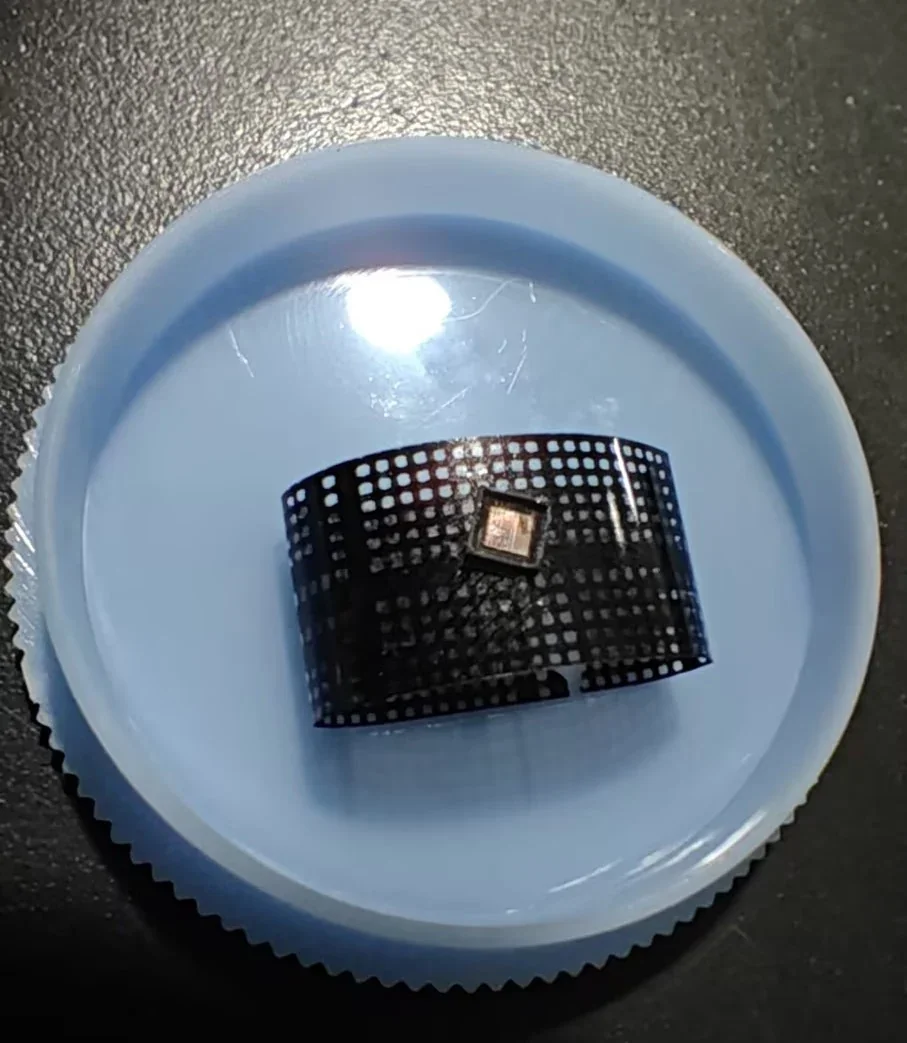
Figure 1 — The workpiece. Mould compound has been removed from the centre of the package and the die sits at the bottom of the cavity, surrounded by the residue ring the laser leaves at the edge of the ablated area. Photographed by the project team, not retouched.
Why 14:1 zoom, not 14X magnification
This is the most common misreading of a lens like this, and it changes every number downstream. The “14X” in the product name is the zoom ratio: the ratio between the lowest and highest optical magnification, 7.6 / 0.55 = 13.8, rounded to 14. The maximum optical magnification is 7.6X, not 14X. A field computed as if the lens reached 14X comes out roughly twice too small, and a resolution figure computed the same way is similarly wrong.
The same caution applies to the camera. 12 MP sounds like a resolution specification, but the lens resolves 2.80 µm at 7.6X while one pixel of a 12 MP 2/3″ sensor covers about 0.28 µm of the object. The sensor is sampling an optical image that is already band-limited by the lens, roughly ten times over. That is not wasted: the extra pixels buy field coverage at the low end and signal-to-noise everywhere. It does mean that upgrading from 12 MP to 20 MP on this lens changes very little about the smallest feature you can see, which is a point covered in more depth in magnification is not resolution.
Inspection sequence
In production the loop is three steps. Locate: at or near 0.55X the package and cavity fit one frame, so the ablation zone can be centred. Zoom: turn to the working magnification; the working distance stays near 78 mm, so the head is not re-positioned, and the focus plane is designed to stay close to the same place, which is what makes the move usable in a cycle. Inspect: check the ablation edge and the die surface, then archive the frame, which is as much a deliverable as the live image.
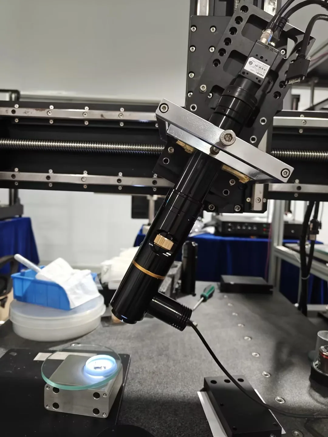
Figure 2 — Bench build of the optical head, inclined roughly 35 degrees from the surface normal so that the path clears the laser position. This is the application-lab set-up used for the imaging trials, not the customer's production cell, and the laser head is not in frame.
What the images show
At the low end the full package is inside the frame with margin, which is what navigation needs. At the high end the die surface resolves into its functional blocks: the regular array of a memory or logic area on one side, the denser analogue or driver structures on the other, and the metal edge of the cavity where the laser stopped.
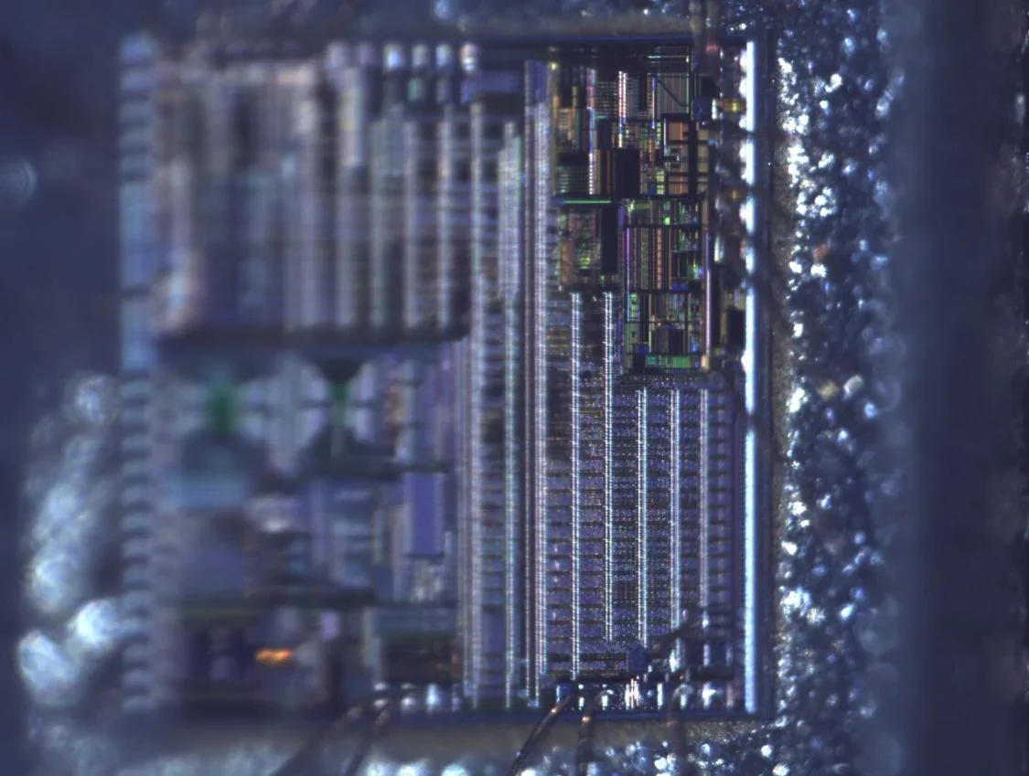
Figure 3 — Die surface at high magnification. The right-hand portion is sharp enough to read individual structures; the left-hand third falls outside the focal band. That gradient is the subject of the next section and is left in the image on purpose.
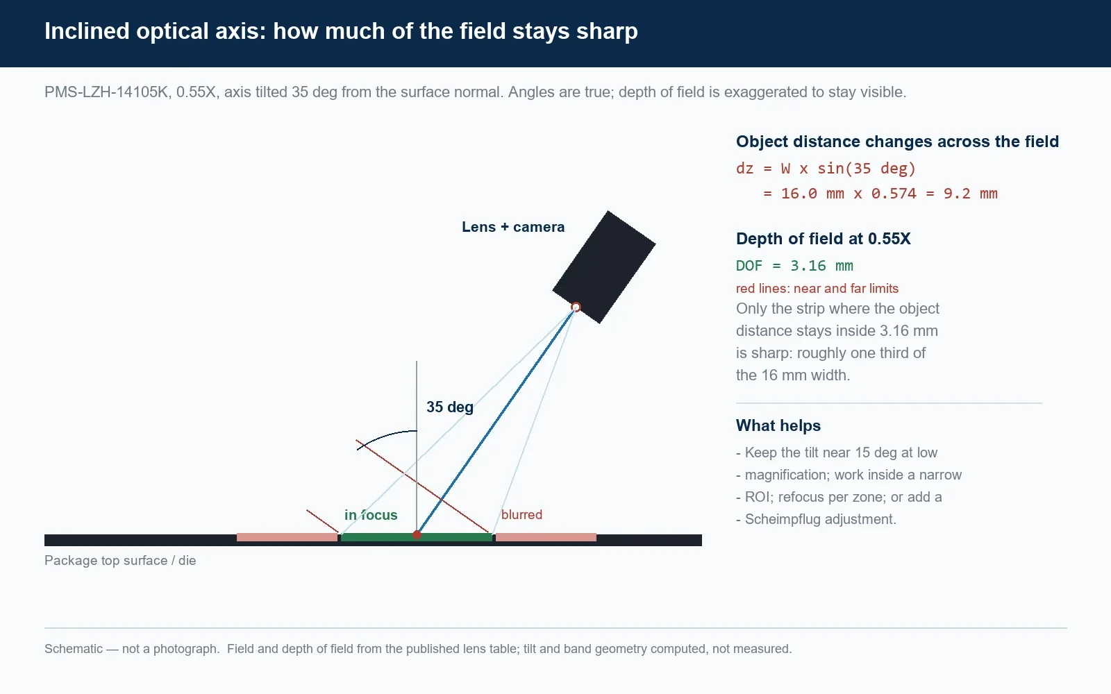
Figure 4 — Schematic, not a photograph. With the axis inclined by 35 degrees, the object distance changes by 9.2 mm across a 16 mm field against 3.16 mm of depth of field.
Engineering limits, including the honest ones
The tilt costs depth of field. When the optical axis is inclined by an angle θ to the surface normal, the object distance changes across the field by Δz = W × sinθ, where W is the field width in the plane of tilt. At 0.55X with a 16 mm field and a 35 degree tilt, Δz = 9.2 mm against a depth of field of 3.16 mm. Only about a third of that width can be inside the focal range at any one focus position. Figure 3 shows exactly this: the sharp band and the soft band are the geometry, not a lens defect.
At high magnification the field shrinks, but the depth of field shrinks faster: at 7.6X the field is 1.16 mm and Δz is 0.67 mm against 0.04 mm of depth of field. Inclined viewing at high power therefore needs a smaller tilt, a narrower region of interest, refocusing between zones, or a Scheimpflug adjustment. A tilt near 15 degrees is a much easier starting point than 35.
No depth measurement was performed. The system images the cavity; it does not measure its depth. Reading depth from focus or from parallax is possible in principle, but it requires calibration against a known step height, and nothing of that kind is recorded in the project file. If decapsulation depth has to be a number rather than an impression, the correct instrument is a confocal or focus-variation sensor, or a triangulation head, not a zoom lens and a 2D camera. The same distinction separates this case from genuine semiconductor inspection tasks that do involve metrology.
Parfocality is a unit property. The project file reports that focus stayed usable across the zoom range. That is a reasonable expectation for this lens family, but parfocality is set at assembly and should be verified on the delivered unit with a test target before the cell is commissioned, not assumed from the datasheet.
Contamination and safety. A 78 mm working distance keeps the front element out of the immediate plume, but the cell still produces particulate and condensable residue, and a protective window is cheaper to replace than a lens. Nothing here addresses laser safety: interlocking, enclosure and filter selection remain the machine builder's responsibility.
Where this configuration fits
The same head suits any cell that removes material from a packaged device and has to watch it happen: laser decapsulation and stripping, laser trimming of passives, marking verification, and rework stations where a die is inspected after lid removal. It also fits work where an inclined view is the only way in.
Questions this case usually raises
What magnification does a 14X zoom lens actually give?
The 14X is the zoom ratio, not the maximum magnification. The PMS-LZH-14105K runs from 0.55X to 7.6X optical magnification, a ratio of about 14:1. With a 2/3-inch sensor that gives a 16 x 12 mm field at the low end and 1.16 x 0.87 mm at 7.6X, so a field calculated as if the lens reached 14X comes out roughly half the real size.
Can one zoom lens cover both chip location and die inspection?
Yes, within the field range above, and that is the reason for the build. At 0.55X the whole package and the opened cavity fit in one frame, which is what locating needs; at 7.6X the die surface resolves into its functional blocks. Because the working distance stays near 78 mm across the range, the head does not have to be re-positioned between the two.
Does mounting the lens at an angle reduce measurement accuracy?
It reduces the sharp area rather than the accuracy of what is sharp. With the axis inclined by 35 degrees, the object distance changes by about 9.2 mm across a 16 mm field against a 3.16 mm depth of field, so only part of the frame is in focus at once. Perspective also compresses one image axis, so any dimension taken from a tilted view needs rectification and a calibration target at the work plane.
Do I need a 12 MP camera to get the most from this lens?
Not for resolution. At 7.6X the lens is specified at 2.80 um, while one pixel of a 12 MP 2/3-inch sensor covers about 0.28 um of the object, so the sensor already oversamples the optical image several times over. The 12 MP sensor earns its place through field coverage at the low end and through the quality of the archived image, not through the smallest feature it can reveal.
Can this set-up measure how deep the laser has cut?
No. It produces a two-dimensional image and a qualitative impression of depth from focus, which is enough to see whether the die is exposed and whether material remains. Turning that into a depth number needs a calibrated instrument such as a confocal or focus-variation sensor, and no depth calibration is recorded in this project.
Request a similar imaging solution
If you are building or retrofitting a laser decapsulation, laser stripping or die inspection cell, send the package size, the feature you must see, the working distance available, the camera model and sensor size, and whether the view has to be inclined. We will answer with a field, a magnification range and a mounting suggestion rather than a catalogue number. Contact POMEAS, or see the PMS-LZH-14105K 14X continuous zoom lens. For the surrounding selection logic, the motorized zoom lens guide and the chip OCR case cover the neighbouring problems.
Related case study: the same zoom-and-inspect approach applied to fine-line inspection of a 512 P/R optical encoder disc with a 12.5X lens.

Subscribe to Our Newsletter
Simply enter your email to receive the latest news and insights from Pomeas. Stay connected with Pomeas and be the first to discover new innovations in optical excellence.


