Knowledge
12.5X Zoom Lens for Optical Encoder Disc Inspection
A 512 P/R incremental encoder carries two tracks of 512 lines each plus a zero-reference window, and a single missing or bridged line becomes a lost pulse or a phase error at the output. This note records a bench inspection of a metal-substrate disc with a POMEAS 12.5X continuous zoom lens, corrects a field-of-view figure that does not survive contact with the actual camera, and separates what the images demonstrate from what they do not.
Project overview
The workpiece is a metal-substrate optical encoder disc, marked 512 P/R, the kind that sits between an LED and a photodetector array inside a rotary encoder and turns angular position into A, B and Z signals. Downstream users are servo motor builders, robot joint and reducer manufacturers, direct-drive turntable and machine-tool encoder suppliers, and automotive steering-angle or throttle sensor makers.
The inspection is a pre-shipment cosmetic and continuity check of the grating after lithography or etching: broken lines, missing lines, bridged lines, edge burrs, etch residue, surface contamination and scratches. It is not an electrical test and it is not a calibration. Everything below should be read with that boundary in mind.
The inspection challenge
The disc in Figure 1 carries several thousand line elements across a handful of concentric tracks, with individual lines a few tens of micrometres wide. At that scale the human eye and a hand magnifier are out of their depth, and a fixed-magnification microscope repeats the problem described in most fine-line inspection work: at low power a break is invisible, at high power you cannot find the place to look.
The second problem is quieter: the defects that matter most barely change the image. A bridged pair of lines differs from a good pair by one dark gap, and a burr changes an edge by a few micrometres. Whether either shows up depends less on magnification than on how the light hits the edge, which is why illumination sits beside optics in this case.
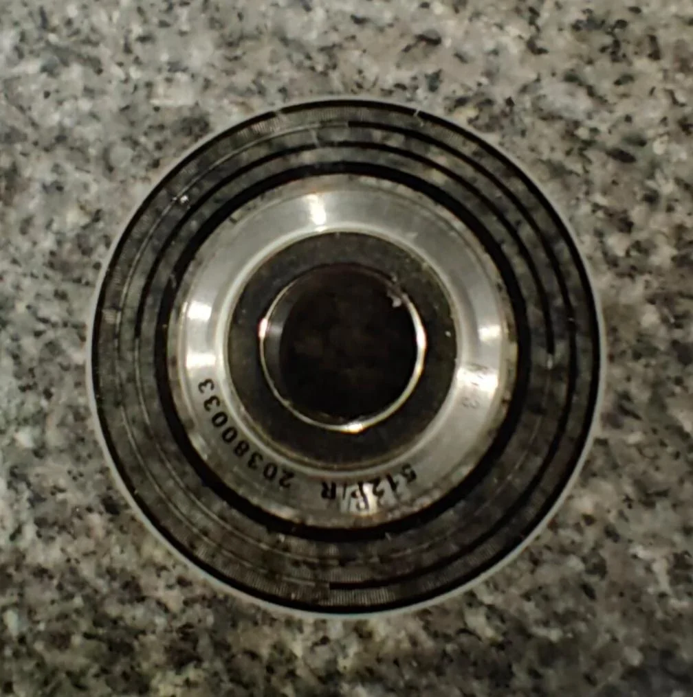
Figure 1 — The workpiece: a 512 P/R metal encoder disc. The concentric tracks are the A and B channels; the engraved 512 P/R marking and the part number sit on the land between the tracks and the hub. Photographed as received, dust included.
Optical configuration
| Item | As recorded | Grade |
|---|---|---|
| Lens | 12.5X continuous zoom, 0.58X–7.5X, WD 77 ± 2 mm, BOM code 63010 + 12101D | A |
| Lens family | LZL-12100 series (manual continuous zoom, 12.5:1, 0.58X–7.5X, WD 77.4 ± 2 mm, 2/3″, C-mount); LZL-12101 is the coaxial variant | B |
| Camera | CCH-020D27CSC-60-A: 2 MP, 1/2″, colour, C-mount, HDMI measurement camera | A |
| Illumination | GH7460-W-1(C) ring light with GE24-4PRT four-channel dimmer | A |
| Stage | Vertical mount, focus knob, XY adjustment, part on a glass plate | A |
| Depth of field | 2.75 mm at 0.58X; 0.27 mm at 2X; 0.05 mm at 7.5X | B |
| Minimum resolution | 3.05 µm (object side, as published) | B |
Two entries need a note. The BOM records the lens as 63010 + 12101D, which is POMEAS internal coding rather than a sales model; the optical figures recorded with it — 0.58X–7.5X and 77 ± 2 mm — match the LZL-12100 series, and 12101D is the coaxial sub-assembly code in that family. Because the recorded illumination is a ring light and no coaxial port is cabled in the bench photograph, this article treats the lens as an LZL-12100-series manual zoom and does not claim the coaxial variant was installed. The LZL-12101 page is the coaxial sibling, useful if the same station later has to look into a recess.
The second note is the camera. The model is a third-party HDMI measurement camera, not a POMEAS product, and its datasheet is not in the project file. Everything that depends on sensor geometry below is therefore computed twice, from two plausible active areas, and flagged as derived.
Field of view: correcting the 18.33 mm figure
The project file states an 18.33 mm field at 0.58X. That number is real, but it belongs to a different sensor. Dividing a 2/3″ diagonal of 11.0 mm by 0.58 gives 18.97 mm; dividing it by 0.6 gives 18.33 mm. In other words 18.33 mm is the 2/3″ figure at 0.60X, carried over into a record whose camera is 1/2″. On the actual camera the same lens gives a smaller field:
| Sensor assumption | Active area | Field at 0.58X | Field at 7.5X |
|---|---|---|---|
| 1/2″, 4:3 nominal | 6.4 × 4.8 mm | 11.03 × 8.28 mm (13.79 mm diagonal) | 0.85 × 0.64 mm (1.07 mm) |
| 1/2″, 1920 × 1080 at 3.75 µm | 7.20 × 4.05 mm | 12.41 × 6.98 mm (14.24 mm diagonal) | 0.96 × 0.54 mm (1.10 mm) |
| 2/3″, for reference only | 8.8 × 6.6 mm | 15.17 × 11.38 mm (18.97 mm diagonal) | 1.17 × 0.88 mm (1.47 mm) |
The difference is not academic. At 18.33 mm a disc of about that diameter fits in one frame at the low end; at 13.8 to 14.2 mm it may not, and the station then has to index around the disc, using the low power for navigation rather than for a single-shot overview. Both computed rows are C-grade: they are correct arithmetic on assumed sensor sizes, and the active area should be read from the camera datasheet before any field is written into a specification.
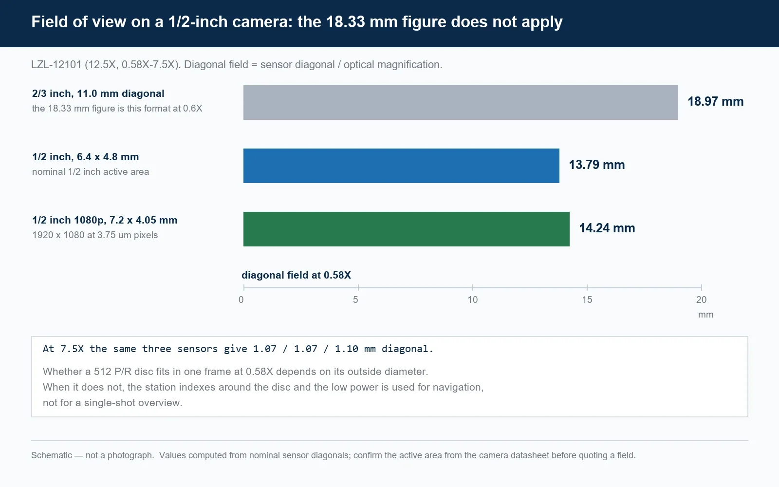
Figure 2 — Schematic, not a photograph. Diagonal field at 0.58X for three sensor formats, showing why the published 18.33 mm figure does not transfer to a 1/2-inch camera.
Illumination: ring light, backlight, and what the images actually use
The BOM lists one ring light. The bench photograph also shows a lit base under the glass plate, and the project text mentions a transmitted backlight. These are not the same claim: a light visible in a photograph is not necessarily part of the delivered configuration, so the backlight is recorded here as unconfirmed.
That distinction matters because the two lights answer different questions. A ring light works in reflection: it puts energy on the metal land and on the line edges, and the contrast in the images below comes from that reflected light. A transmitted backlight works through the part: it produces bright windows wherever the substrate is transparent and dark wherever material blocks it, which is the natural way to find a broken line on a glass or film scale. On an opaque metal disc there is nothing to transmit through, so a backlight contributes little to line contrast and mostly helps with edge location and with seeing through the central bore.
If one station must handle both metal and glass discs, the light has to be switchable and the recipe must record which light produced each result. A defect visible under one illumination and not the other is a normal outcome, not a contradiction.
Inspection sequence
Navigate. Start at 0.58X, confirm the track layout, count the tracks, and read the 512 P/R marking to be sure the right part is on the stage. If the disc does not fit the field, index around it and note the angular positions covered.
Zoom. Turn to the working magnification. Depth of field falls quickly: 2.75 mm at 0.58X becomes 0.27 mm at 2X and 0.05 mm at 7.5X, so focus is set once per zone at high power and the stage is not touched between frames.
Scan and record. Work radially along one track, then the next, and archive each frame with its position. A defect without a position is not actionable for the engineer who has to fix the etcher.
What the images show
Figure 3 covers three concentric tracks plus the engraved marking in one view, which is the navigation frame. Figure 4 is the same disc at high magnification, where individual lines, their edges and the metal land between tracks are resolved.
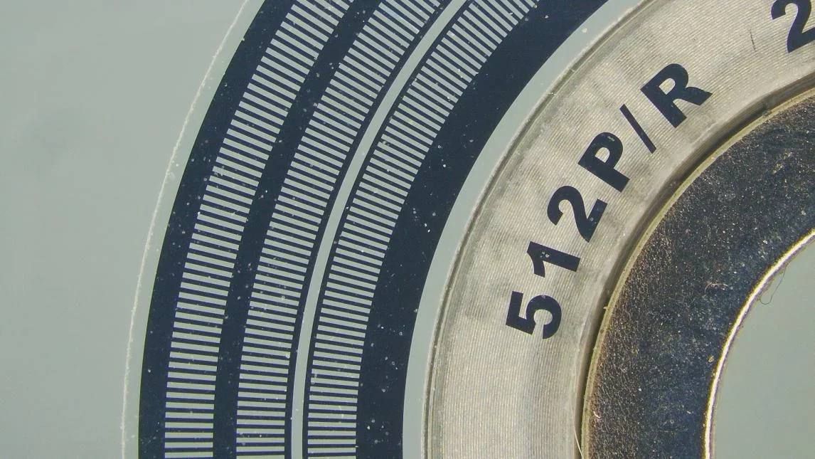
Figure 3 — Low-magnification view. Three concentric tracks and the 512 P/R engraving are in one frame; the scattered bright specks are loose particles on the metal surface, not grating defects.
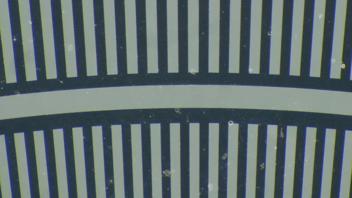
Figure 4 — High-magnification view of two tracks. Line edges are clean and continuous across this field; the visible artefacts are particles sitting on the land between tracks. No broken or bridged line was recorded in this frame, and none is claimed.
Engineering limits and what was not verified
The images demonstrate image quality, not detection performance. There is no record of a 100 percent inspection of all 512 lines per track, no defect library with known ground truth, and no repeatability study. A frame that resolves a 30 µm line and a 3 µm edge irregularity is a precondition for reliable detection, not evidence of it. Proving detection performance needs seeded defects and a measurement of escape rate.
3.05 µm is a lens specification, not an inspection capability. It describes the finest detail the lens can transfer at the object plane under nominal conditions. The smallest defect a station can call reliably is set by contrast, by illumination, by pixel sampling at the chosen magnification, and by the decision rule. It is normally several times coarser than the lens figure, and it should be measured on real parts.
Appearance inspection is not electrical test. A disc can look perfect and still fail on phase error, duty cycle or signal amplitude; a disc with a marginal line can pass both. Nothing here measures the A/B signal, the phase relationship or the interpolation error, and the article makes no claim about encoder accuracy.
Sampling at low magnification. With a 2 MP 1/2″ camera, one pixel covers about 6.5 µm of the object at 0.58X and about 0.5 µm at 7.5X, against a lens resolution of 3.05 µm. At the low end the camera is the limiting term, at the high end the lens is; this is the practical reason the low power is used for navigation and the high power for judgement.
Distortion. The project file quotes TV distortion of 0.05 percent or better. The current product page for the family lists a minimum TV distortion of 0.001 percent, and the two figures do not reconcile. Distortion should be taken from the datasheet revision that ships with the lens, and measured if dimensional work is intended.
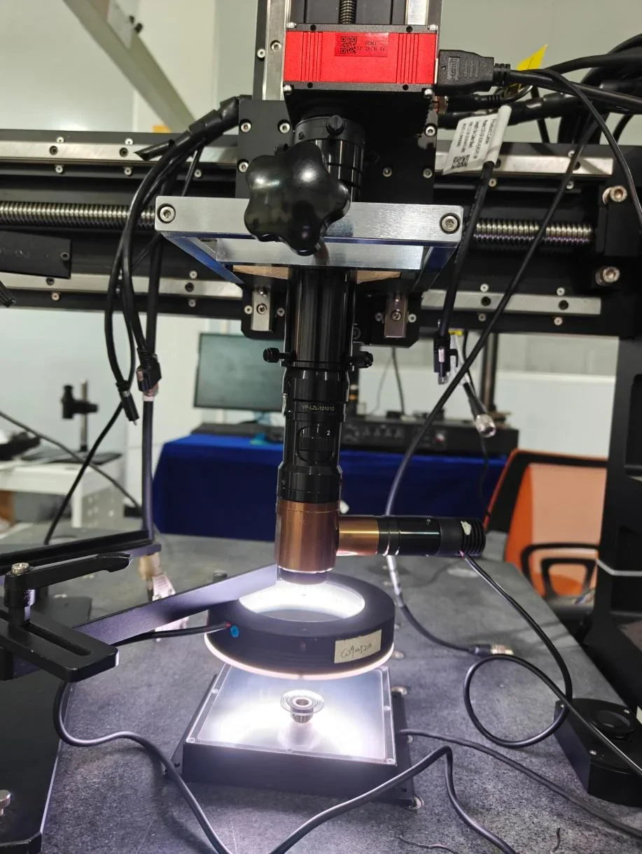
Figure 5 — Bench set-up. Vertical mount with focus knob and XY adjustment, ring light at the lens, disc on a glass plate over a lit base. The backlight visible here is not itemised in the BOM.
Where this configuration fits
Any fine-line part that has to be searched over a large area and judged at high magnification is a candidate: encoder and scale discs, linear glass scales, reticles and masks, etched meshes, thin-film resistor patterns and flex-circuit trace arrays. The same range suits rework and incoming inspection, where the operator has to find a defect first and characterise it second.
Questions this case usually raises
What field of view does a 12.5X lens give on a 1/2-inch camera?
About 11.0 x 8.3 mm at 0.58X and 0.85 x 0.64 mm at 7.5X, assuming a nominal 6.4 x 4.8 mm active area. If the camera is a 1920 x 1080 sensor with 3.75 um pixels the low-end field becomes 12.4 x 7.0 mm. The 18.33 mm figure that circulates for this lens is a 2/3-inch value at 0.6X and does not apply to a 1/2-inch camera.
Is 3.05 um the smallest defect this lens can detect?
No. 3.05 um is the published optical resolution at the object plane, not an inspection capability. What a station detects reliably depends on contrast, illumination, pixel sampling and the decision rule, and is normally several times coarser. It has to be established on real parts with seeded defects rather than read from a datasheet.
Ring light or backlight for encoder disc inspection?
Ring light for surface features on an opaque metal disc, where line edges, burrs, bridges and contamination are seen in reflection. Backlight for transparent or film scales, where a broken line shows up as a change in transmitted light. If both part types are planned, the station needs both lights and the inspection recipe must record which one was used for each result.
Can this inspection station replace the electrical test of the encoder?
No. It checks the grating, which is only one failure cause. Phase error, duty cycle, signal amplitude and interpolation accuracy are electrical properties measured with the disc running in an encoder. Optical inspection and electrical test are complementary, and this case makes no claim about encoder signal performance.
Why not use a fixed-magnification microscope for a 512 P/R disc?
Because the area to search is large and the defect is small. A fixed low power cannot resolve a break and a fixed high power cannot find it. A 12.5:1 zoom keeps one mount and one working distance while covering both the navigation view and the judgement view, which is what makes bench inspection of a whole disc practical.
Request a similar inspection solution
Send the disc or scale outside diameter, the line width and pitch, the smallest defect you must catch, the camera model and sensor size, the working distance available, and whether the part is opaque or transparent. We will reply with a magnification range, a field table and an illumination proposal rather than a single part number. Contact POMEAS, or start from the LZL-12100 12.5X continuous zoom lens and the 12.5X model comparison. For the step before this one, choosing between zoom families, the 6.5X versus 12.5X guide covers the trade-offs.
Related case study: a 14X zoom lens used inside a laser decapsulation cell, where the optical axis has to be inclined and depth of field becomes the limiting factor.

Subscribe to Our Newsletter
Simply enter your email to receive the latest news and insights from Pomeas. Stay connected with Pomeas and be the first to discover new innovations in optical excellence.


