Knowledge
Zoom Lens for Medical Device Inspection: Selection Rules
Medical device inspection asks three things that general industrial inspection does not: the part is often transparent or liquid-filled, the equipment must live in a controlled environment, and the image may have to become part of a record that someone will audit. A zoom lens fits these constraints well when it is chosen for the right reason, and badly when it is chosen because it is flexible. This article sets out the four optical requirements that actually decide the lens for medical components, then the environmental and documentation constraints that eliminate otherwise suitable options.
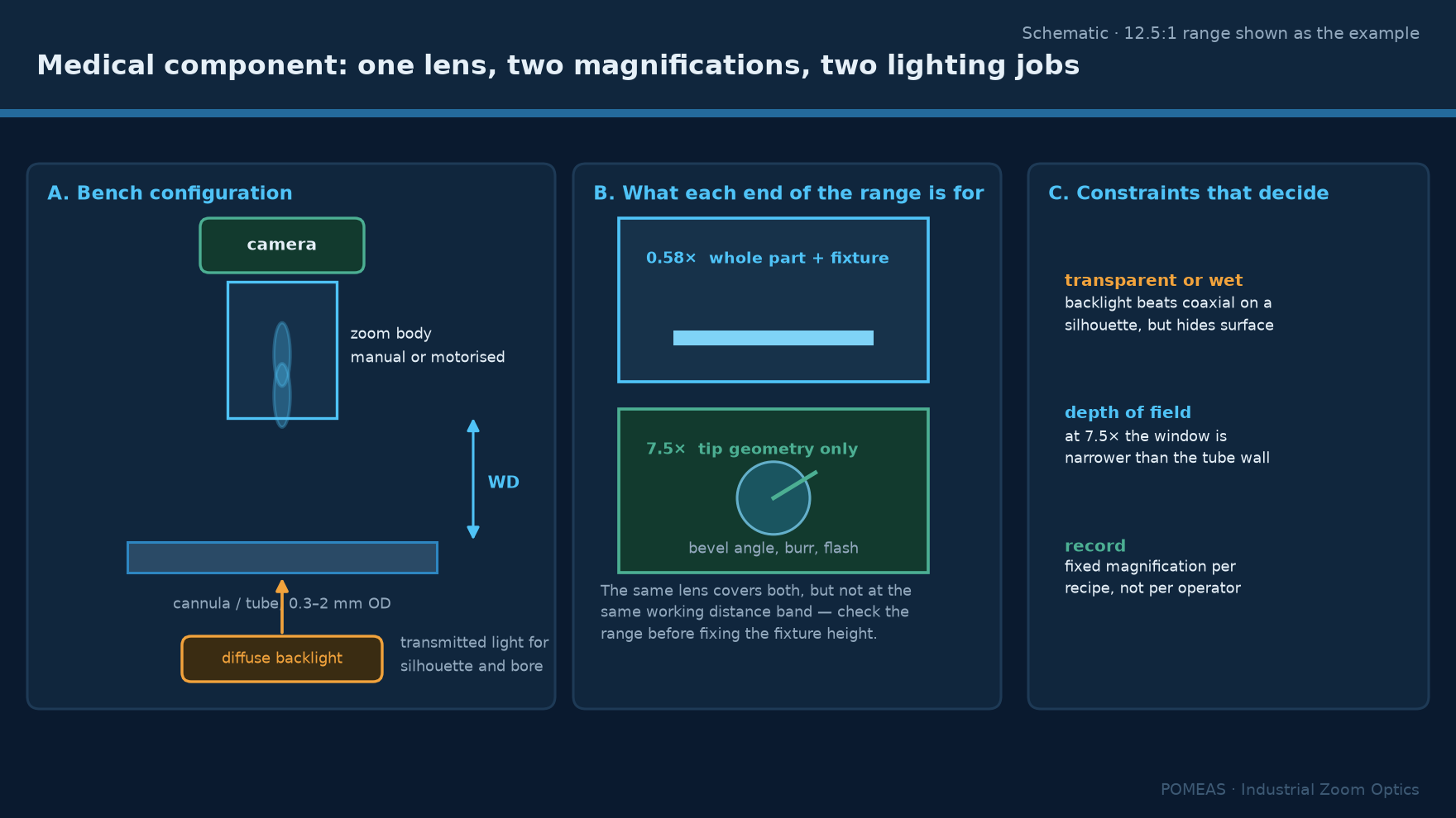
Requirement one: the part is often transparent or wet
Cannulae, catheter tubes, syringe barrels, blister packs and lens implants are transparent or translucent, and many are inspected wet or filled. This changes the contrast mechanism from reflective to transmissive or refractive, which means the illumination strategy has to be decided before the lens. Backlight makes a transparent tube into a silhouette and is the most reliable way to see a lumen or a wall thickness; dark field makes a scratch on a clear surface visible; coaxial light on a transparent part produces a double reflection from the near and far walls that can be mistaken for a defect.
The optical consequence is that working distance must stay constant as magnification changes, because changing the distance between the lens and the part changes the illumination angle and therefore the contrast. A zoom lens that holds its working distance across its range is therefore worth more than one with a wider range but a shifting distance. Across the POMEAS families the 6.5× range holds 87 ± 2 mm, the 12.5× range holds 77.4 ± 2 mm, and the 14× range holds 77.8 ± 2 mm.
Requirement two: dimensions and defects are different jobs
A medical component typically needs both. A needle bevel needs a dimensional check of the tip angle and a cosmetic check for a burr. A stent needs strut width and a check for cracks. Those two checks have different optical requirements: a dimension needs a calibrated scale and low distortion, a cosmetic check needs contrast and resolution. One zoom lens can do the cosmetic check across a range of part sizes; it cannot certify a dimension, because its magnification is not a calibrated reference and its distortion changes with zoom position.
The honest division is: a zoom lens for finding, characterising and documenting; a telecentric system or a measuring machine for the dimension that appears on a drawing. Where a single system must do both, the dimension is measured by a telecentric lens and the zoom lens is a second optical path, not a substitute.
Requirement three: the field must follow the part range
Medical device portfolios tend to span a wide size range: a 0.2 mm needle tip and a 30 mm syringe barrel in the same building. A zoom lens lets one station cover that range without a lens change, which is valuable in a cleanroom where every intervention is a contamination risk and every tool change is a line clearance.
| Component | Feature to judge | Field needed | Magnification on 2/3″ |
|---|---|---|---|
| Needle tip, bevel and burr | 0.02 mm burr, tip angle | 1.5 mm | 5.9× |
| Cannula lumen and wall | Wall thickness, flash | 4 mm | 2.2× |
| Catheter tip hole | Hole roundness, burr | 6 mm | 1.5× |
| Syringe barrel graduation | Print legibility | 15 mm | 0.58× |
| Stent strut | 0.08 mm strut, crack | 1.2 mm | 7.3× |
| Blister seal | Seal width, channel | 20 mm | 0.44×, outside 12.5× range |
The last row is the useful one: a 20 mm field on a 2/3-inch sensor needs 0.44×, which a 12.5× lens cannot reach, while a 1-inch 4K zoom lens at 0.68× gives 18.8 mm and a 0.58× setting on the 12.5× range gives 15.17 mm. Blister seal inspection is therefore a 1-inch sensor job or a wider lens family, not a matter of zooming further out.
Requirement four: the record must be reproducible
If the inspection image becomes part of a quality record, three properties matter. The magnification has to be known, so that a measurement or a size comparison in the image can be interpreted later. The illumination has to be recorded or reproduced, because contrast depends on it. And the same setting has to be recoverable, so that a re-inspection six months later uses the same optical configuration.
A manual zoom lens with a scale ring satisfies the first property only approximately and the third not at all. A motorised lens with position feedback satisfies all three, provided the position is stored with the image. This is the strongest argument for a motorised lens in a regulated environment, and it has nothing to do with image quality.
Whether a specific record needs to be attributable, contemporaneous and tamper-evident depends on the quality system that applies to the product; that is a compliance question for the manufacturer, not an optical one. What the optics can do is make the optical state of the image knowable, which is a precondition for any of it.
Environmental constraints that eliminate options
Cleanroom compatibility rules out lenses with exposed lubricated mechanisms, and it also rules out forced-air cooling anywhere near the optics. A zoom lens with a sealed or low-shedding mechanism is preferable, and a motorised lens should be evaluated for particle generation at the cable entry, which is where most shedding occurs.
Cleaning agents are the second constraint. A lens that will be wiped with alcohol daily needs a front element that tolerates it, and a lens with a recessed front element is easier to clean than one with a protruding cone. The 6.5× and 12.5× families are cylindrical with a flat front, which is straightforward to wipe; a lens with a narrow snout is not.
The third is mounting. In a cleanroom transfer window or a laminar flow hood, the optical path is often vertical and short, so the camera and lens assembly must fit inside the hood without disturbing the airflow. A 77 mm working distance plus a camera body is roughly 150 mm of vertical stack, which is worth checking against the hood height before ordering.
What to avoid claiming
A zoom lens does not make an inspection validated, does not establish a measurement uncertainty, and does not by itself satisfy any regulatory requirement. Those are properties of a validated process, not of an optical component. What can be stated is narrower and more useful: the lens provides a known field of view at a known working distance with a stated optical resolution, and at high magnification the smallest resolvable feature is set by that resolution rather than by the camera.
For a 14× class lens that limit is 2.80 µm at 5× and above, which means a 5 µm burr is resolvable and a 1 µm one is not. Stating that boundary up front prevents the most common project failure in medical optical inspection, which is a specification written around a feature the optics cannot resolve.
Frequently asked questions
Can a zoom lens replace a measuring microscope for medical components?
Not for dimensions. A zoom lens has no calibrated magnification reference and its distortion varies with zoom position, so a measurement taken from its image is not traceable. It can find, characterise and document a defect, and a telecentric system or measuring machine should carry the dimensional call.
What magnification is needed to inspect a needle tip?
A 1.5 mm field on a 2/3-inch sensor needs about 5.9×, which is inside the 12.5× family range and gives roughly 0.78 µm per pixel at 1920 pixels wide. That is finer than the 3.05 µm optical resolution, so the camera is not the limit and a 2 to 5 megapixel sensor is sufficient.
Is coaxial illumination suitable for transparent components?
Usually not. On a clear tube or barrel the front and back walls both reflect, producing two overlapping images. Backlight for silhouette and dark field for surface defects are more reliable on transparent parts, and coaxial is better reserved for reflective metal components such as a stainless needle.
Can the lens be used inside a laminar flow hood?
Physically yes if the vertical stack fits, but verify two things: that the assembly does not disturb the airflow enough to break the laminar envelope, and that the lens mechanism does not shed particles. A cylindrical lens with a sealed mechanism and a flat front element is the easier case.
How do I record the magnification with the image?
Use a motorised lens that reports position over its control interface and write that value into the image metadata or the inspection record. A manual lens with a scale ring gives an approximate value that is not reproducible between operators.
What field can a 6.5× lens cover?
At 0.7× on the PMS-LZ-63102-M12 with a 2/3-inch sensor the field is 12.6 mm wide; at 4.5× it is 2.0 mm. The 87 ± 2 mm working distance stays constant across that range, which is useful where the illumination geometry must not change between magnifications.

Subscribe to Our Newsletter
Simply enter your email to receive the latest news and insights from Pomeas. Stay connected with Pomeas and be the first to discover new innovations in optical excellence.


