Knowledge
Zoom Lens with APO Objectives: Magnification, Vignetting and Industrial Applications
This article is also available in 简体中文.
Quick answer: total magnification = zoom body × TV tube × APO objective. A 6.5X zoom body with a 2× APO objective spans roughly 1.4×–9× (computed by multiplication — no official combination table exists yet). Vignetting, when it occurs, concentrates at the low-magnification end: internal measurements show the illuminated field shrinking to a circle of 1774 px — 72.5% of a 2/3″ sensor's width — with zero corner brightness. Confirm vignetting acceptance and request data for your exact combination before ordering.
Pairing a continuous zoom lens with APO (apochromatic) objectives is the standard way to build a wide-range industrial microscopy system: one lens covers everything from board-level overviews to sub-micron detail, without changing optics. This guide explains how the combined magnification is calculated, why vignetting can appear at the low-magnification end, and what to confirm before you commit to a combination.
1. How the combination works
A typical POMEAS setup stacks three optical stages:
Zoom body × TV tube × front objective = total optical magnification.
For example, the LZ-650104 motorized zoom lens covers 0.7×–4.5× (6.5:1 ratio, WD 82±2 mm, 2/3″ sensor). The LZL-12100 covers 0.58×–7.5× (12.5:1, WD 77.4±2 mm) with a telecentric design. Front-mounted MPO APO objectives add a fixed factor:
| APO objective | NA | Working distance | Resolution | Depth of field |
|---|---|---|---|---|
| 2× | 0.055 | 34.6 mm | 5 μm | 91 μm |
| 5× | 0.14 | 45 mm | 2 μm | 14 μm |
| 10× | 0.28 | 34 mm | 1 μm | 3.5 μm |
| 20× | 0.29 | 30.8 mm | 0.7 μm | 3.5 μm |
| 50× | 0.42 | 20.5 mm | 1 μm | 1.6 μm |
Values from the POMEAS MPO objective datasheet. Working distance is not monotonic: the 5× objective has the longest WD at 45 mm, while the 50× works at 20.5 mm.
Theoretical combined ranges with a 1× TV tube, for illustration:
- 6.5X zoom + 2× APO → 1.4×–9×
- 6.5X zoom + 5× APO → 3.5×–22.5×
- 12.5X zoom + 10× APO → 5.8×–75×
Caution: these values are computed by multiplication only. POMEAS datasheets do not yet publish a zoom+APO combination table (MTF, FOV or vignetting), so treat combination values as estimates until they are verified for your specific setup.
2. Optical magnification, display magnification and resolution — three different numbers
- Optical magnification is the image-to-object ratio on the sensor: zoom × tube × objective. Selection, quotations and drawings should always use this number.
- Display magnification = optical magnification × (screen size ÷ sensor size). The same 5× optical image looks far larger on a 27″ monitor than on the sensor, but nothing about the optics changed. Never quote display magnification.
- Optical resolution is the smallest object detail the lens can resolve (μm). It is limited by the numerical aperture (resolution ≈ 0.61λ/NA, λ ≈ 0.55 μm) and, in practice, by the camera pixel size projected to the object plane (pixel size ÷ total magnification). With a 3.45 μm-pixel 2/3″ camera at 9×, the pixel-limited resolution is ≈0.38 μm — finer than the 2× objective's 5 μm optical rating, so the camera is not the bottleneck at the high end. At the low-magnification end the opposite holds: the optics, not the sensor, set the limit.
Practical rule: match the objective NA to the detail size you must resolve, then use the zoom range for framing — not the other way round.
3. Field of view: a two-line calculation
FOV = sensor dimension ÷ total magnification. With a 2/3″ sensor (8.8 × 6.6 mm):
- 6.5X zoom + 2× APO at 1.4× → 6.3 × 4.7 mm
- same setup at 9× → 0.98 × 0.73 mm
- 6.5X zoom + 5× APO at 22.5× → 0.39 × 0.29 mm
A useful cross-check from the same datasheets: the MPO objectives' rated field (Φ12 mm down to Φ0.48 mm) follows FN ÷ magnification with an FN-24 reference — internal consistency you can rely on when planning coverage across magnification steps.
4. Vignetting at low magnification: what the measurement data shows
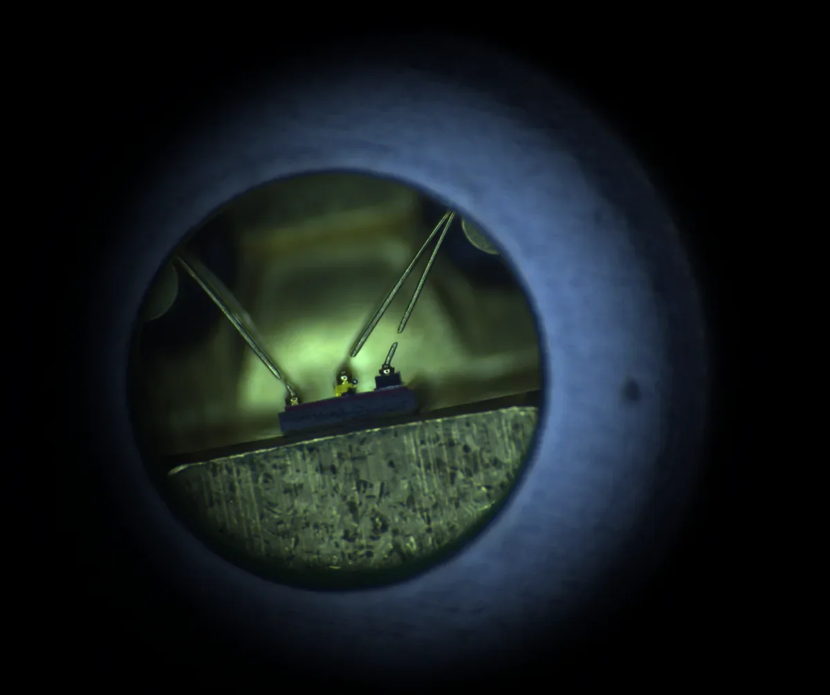
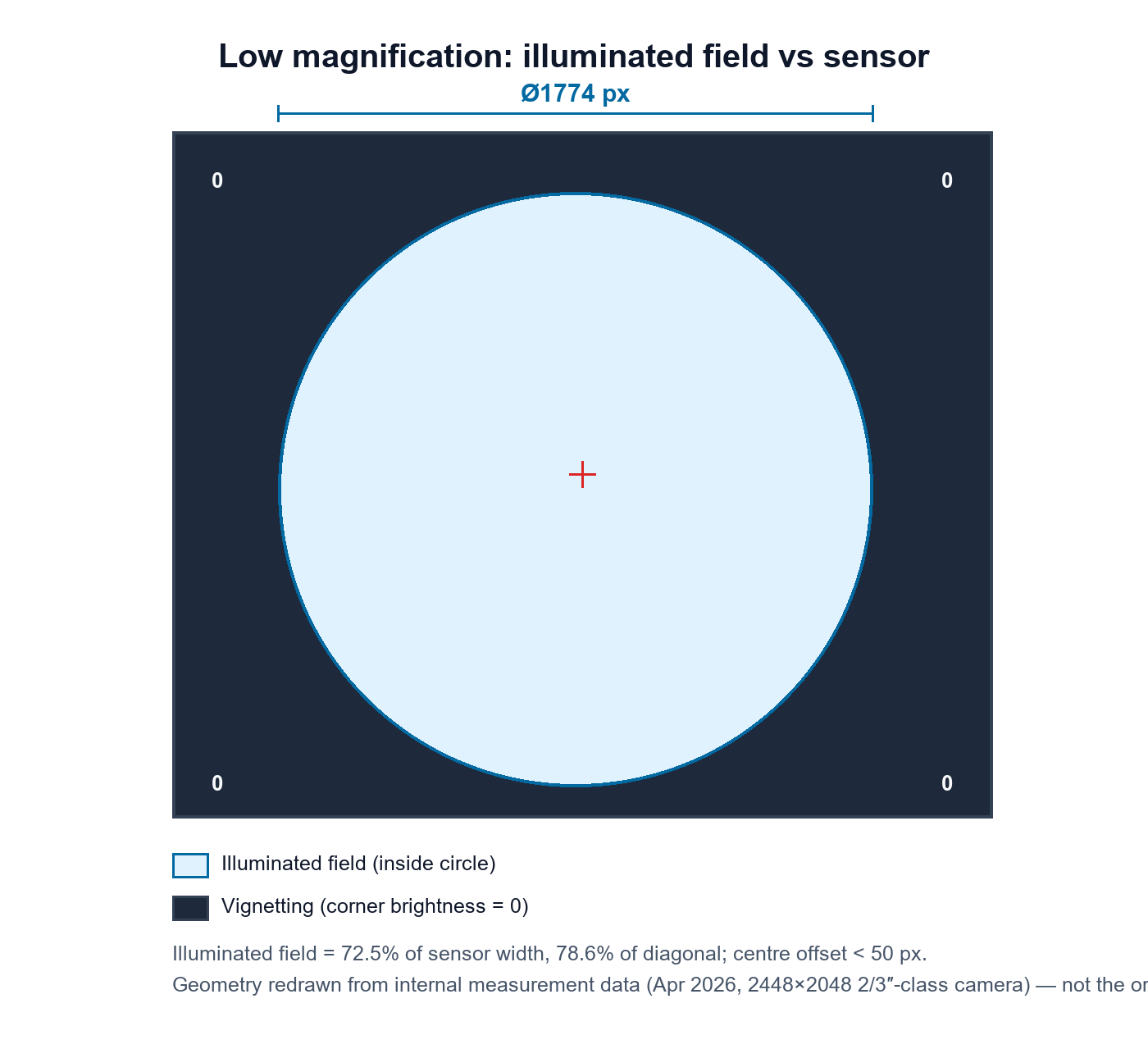
Low-magnification end (POMEAS internal test, April 2026): the illuminated field contracts into a sharp circle of 1774 px diameter — 72.5% of the 2/3″ sensor's width, 78.6% of its diagonal — and the corners receive no light at all. Magnification is not annotated on the raw image.
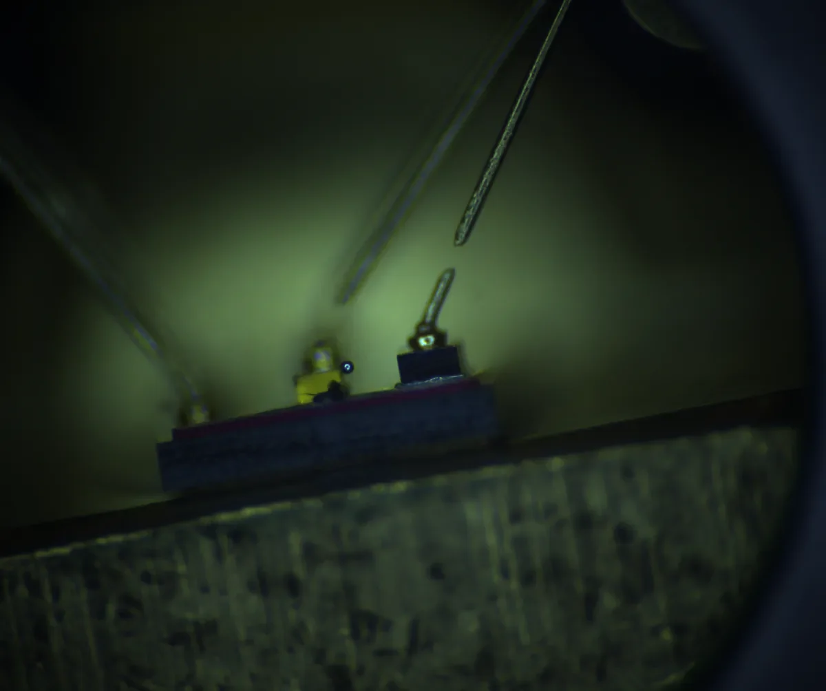
The same sample after raising the magnification: corners regain brightness, the hard field-circle boundary disappears, and the corner-to-centre brightness gap narrows from −100% to about −82%.
Internal measurements (April 2026, 2448 × 2048 2/3″-class camera) quantify the phenomenon:
- At the low-magnification end, the illuminated field forms a circle of 1774 px diameter — about 72% of the sensor width and 79% of its diagonal — centred within 50 px of the sensor centre; the corners drop to zero brightness.
- On the same sample at a higher magnification, corners retain brightness and the hard circular boundary disappears; the measured corner-to-centre brightness gap narrows from −100% to about −82%.
In other words: vignetting, when it occurs in zoom systems, concentrates at the low-magnification end, because the field of view is largest there relative to the usable image circle. This matches the manufacturer's own selection charts, which mark with parentheses exactly those low-magnification cells where vignetting will occur in actual use — for example, wide-angle attachments (0.25×–0.75×) on a 2/3″ sensor behind a 0.5× camera adapter.
Two cautions. First, this does not mean every APO objective vignettes: the published vignetting marks cover the 0.25×–2× attachment range, and no zoom+APO combination table has been published. Any claim that vignetting disappears above 2× should be restricted to combinations where it has actually been verified. Second, vignetting is partly a matter of acceptance: for overview tasks a slightly dark corner is often tolerable, for photometric or measurement-critical imaging it is not — confirm acceptance before ordering.
5. What to confirm before ordering
- The vignetting acceptance criterion — will corners be used, or is the central field sufficient? Ask for a sample image at your working magnification.
- Sensor size vs image circle — larger sensors need higher-magnification TV tubes; the 4K series chart, for instance, supports 1″ sensors only from 1× tubes upward and φ32 mm only at 2×.
- WD budget — APO objectives place the front element 20–45 mm from the sample; add fixture clearance.
- Lighting — coaxial illumination behaves differently through the objective; confirm with your sample.
- Verified data — request the combination FOV/vignetting sheet for your exact zoom + tube + objective stack.
6. Industrial applications
| Application | Typical starting point | Key parameter | Selection limit |
|---|---|---|---|
| Semiconductor defect inspection | 12.5X zoom + 10× APO | resolution ≈1 μm, WD 34 mm | verify MTF at the high-zoom end |
| IC surface inspection | 6.5X–12.5X + 2×–5× APO | overview → detail in one stack | low-mag vignetting acceptance |
| PCB micro-defect detection | 6.5X + 2× APO, 2/3″ sensor | FOV ≈6.3 × 4.7 mm at 1.4× | track width vs NA |
| Precision dimensional measurement | telecentric 12.5X body | low TV distortion | measurement needs calibration, not just magnification |
| Wafer inspection | motorized 12.5X/14X + 5×–20× APO | motorized repeatability | WD 20–45 mm stage clearance |
| Microstructure imaging | 50× APO (NA 0.42) | DoF 1.6 μm | focus stability critical |
| Automated optical inspection (AOI) | motorized zoom + preset positions | position repeatability | verify repeatability spec per model |
| Industrial microscopy (general) | any zoom + 2×/5× APO | zoom ratio 6.5:1–14:1 | — |
| Motorized zoom + autofocus | LZL/DS9 motorized bodies | RS-232 control, motorized focus trim | AF is focus trim, not true autofocus — confirm |
Related reading: the complete motorized zoom lens selection and integration guide compares the zoom-body families, RS-232 control paths and integration practice in depth.
Deep dives: why corners go dark at low magnification · APO vs plan achromatic vs achromatic objectives · magnification & FOV worked examples · sensor & image-circle matching · semiconductor & wafer applications · 5-step selection checklist
Need help matching a zoom body, TV tube and APO objective to your sensor and working distance? Contact POMEAS with your detail size, sensor format and WD budget.

Subscribe to Our Newsletter
Simply enter your email to receive the latest news and insights from Pomeas. Stay connected with Pomeas and be the first to discover new innovations in optical excellence.


