Knowledge
V-Groove and Fiber Array (FAU) End-Face Inspection: Telecentric and Microscope Imaging Options
In optical device packaging, fibers are no longer inspected only one connector at a time. V-groove substrates and fiber array units (FAU) place 4, 8 or more polished fiber ends side by side on a single glass or silicon substrate, and the quality of that whole row decides the coupling loss of the final device. This article describes what a V-groove / FAU end-face inspection has to show, why it is harder than a single connector end face, and which imaging and illumination combinations fit the two working scales involved — illustrated with four real camera images of a 4-fiber V-groove sample.
Other languages: 中文 · Español · Français · Русский · العربية
Part of the POMEAS Machine Vision Inspection Application Cases series — see the Machine Vision Inspection Application Cases index for all 20 articles in this set, grouped by industry.
1. What the Inspection Has to Show
A fiber array end face is judged on the row of fiber ends seated in the V-grooves. In practice the checklist covers:
- Fiber presence and position — every designed groove holds a fiber, at the expected pitch, with no empty groove and no crossed fiber.
- Fiber end height (protrusion or recession) — the polished fiber end must sit at the designed height relative to the substrate end face; a protruding or recessed fiber changes the coupling gap.
- Core/cladding concentricity on the image — under magnification, the bright core spot should sit inside the cladding ring, centered well enough for the coupling budget.
- End-face contamination — dust, lint fibers, polishing residue or adhesive bleed anywhere on the row or in a groove.
- Substrate end-face condition — chips, scratches or glue marks on the glass substrate edge that could mislead downstream assembly.
The two imaging scales are different jobs. The array overview asks "is every fiber present and seated, and is the row clean?" — a field of view of several millimeters. The single-fiber view asks "is this core centered and this end clean?" — a field of view around one fiber. A workable inspection station needs both, or a smoothly variable middle ground.
2. Why It Is Harder Than a Single Connector End Face
Three properties of V-groove samples drive the optical choice:
- Mixed reflectivity. The polished fiber end is a small, bright, mirror-like target; the glass substrate around it is a large, low-contrast surface. An illumination that makes the fiber ends pop can wash out the substrate, and vice versa.
- Two scales in one part. With a 125 µm cladding diameter (typical for standard fiber) and groove pitch of a few hundred micrometers, the interesting features are at the edge of what one fixed magnification can cover on a standard sensor.
- Height structure. The fiber ends sit slightly below or flush with the substrate surface, inside grooves. Light arriving at the wrong angle shadows the grooves and hides the fiber ends; light arriving along the optical axis reaches into them.
3. Array Overview: Coaxial Telecentric Imaging
For the top view of the whole row, a telecentric lens with built-in coaxial illumination is the natural fit. Coaxial light travels down the imaging axis, so it reaches into the shallow grooves and returns from the flat, polished fiber ends — exactly the geometry the sample below was imaged with. Telecentric optics keep the pitch measurement between adjacent fiber ends undistorted by perspective, which matters when the pitch value itself is a judged quantity.
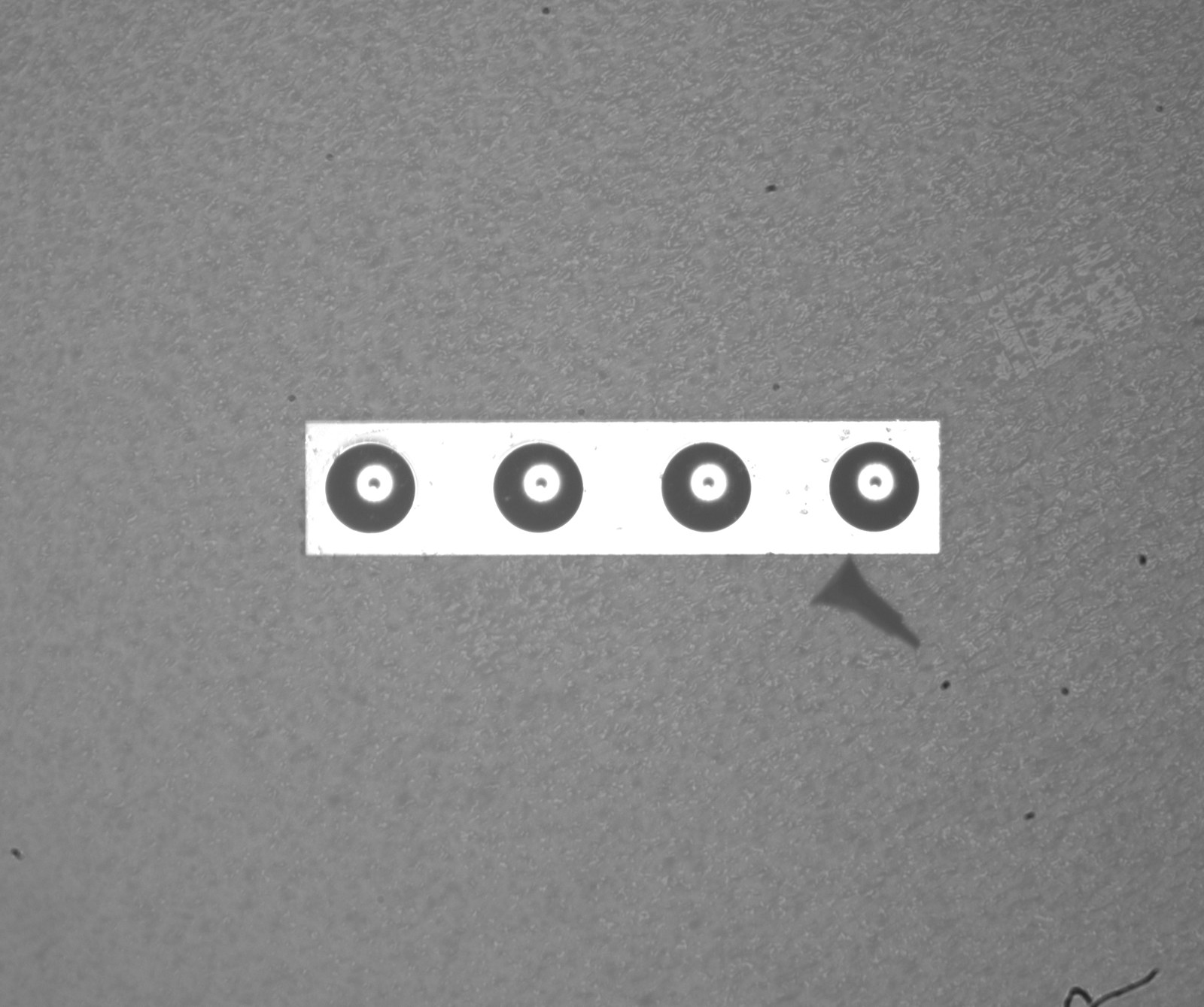
In the image above, all four fiber ends are clearly resolved: each shows a bright core spot inside a dark cladding circle, and the four ends sit at an even pitch on the bright substrate strip. This is the "is the row complete and seated" view — the frame a production line can judge in a fraction of a second.
For this scale, the telecentric product family covers the working distances and fields of view typical for FAU substrates; for example, a 2X coaxial telecentric model is listed here, and the full telecentric range is under telecentric lenses.
4. Detail View: Zoom or Microscope Optics on a Single Fiber End
When the judged quantity moves to a single fiber end — core concentricity, a contamination particle, polish quality — the array view no longer has enough pixels on the target. Two stacked-optics routes cover this:
- Zoom lens + APO objective. A continuous-zoom body with a coaxial beam-splitter port, converted through an APO adapter ring to an APO objective, sweeps one station from overview to detail. The conversion carries a mandatory factor: total magnification = zoom magnification × APO objective magnification × 0.55, where 0.55 is the coupling factor of the APO adapter ring. Skipping it corrupts every field-of-view and pixel-size calculation downstream. A delivered connector-end-face case built on exactly this route is documented in our fiber end-face inspection case.
- Microscope optics. Where the station is dedicated to one fiber end at a time, a measuring microscope or a fixed-magnification microscope objective on a coaxial port gives the highest numerical aperture and the shortest, most stable optical train.
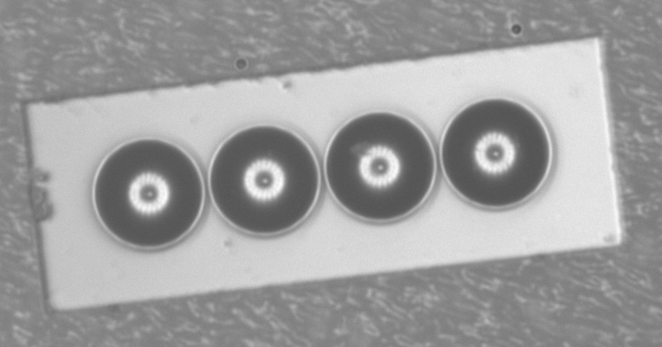
The close-up below is the same 4-fiber sample imaged at higher magnification: the core spot, the cladding ring and the fine diffraction texture around each core are all resolved — the level of detail at which concentricity and surface contamination judgments become possible.
5. Contamination Is the Defect the Camera Sees First
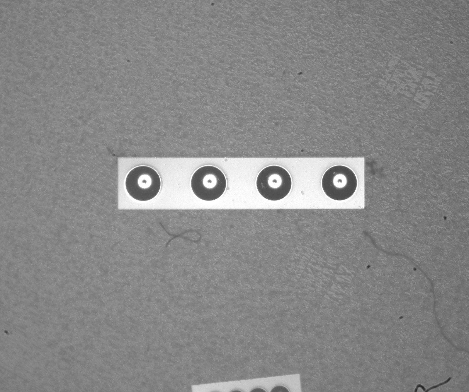
On real samples, the most frequent visible defect is not a bad polish — it is contamination. The image below shows the same type of substrate with a loose lint fiber lying across the scene near the row. A defect of this kind is obvious at the array scale, which is a second reason to keep the overview station in the process rather than jumping straight to high magnification.
6. The Rail View: Checking Groove Geometry from the Side
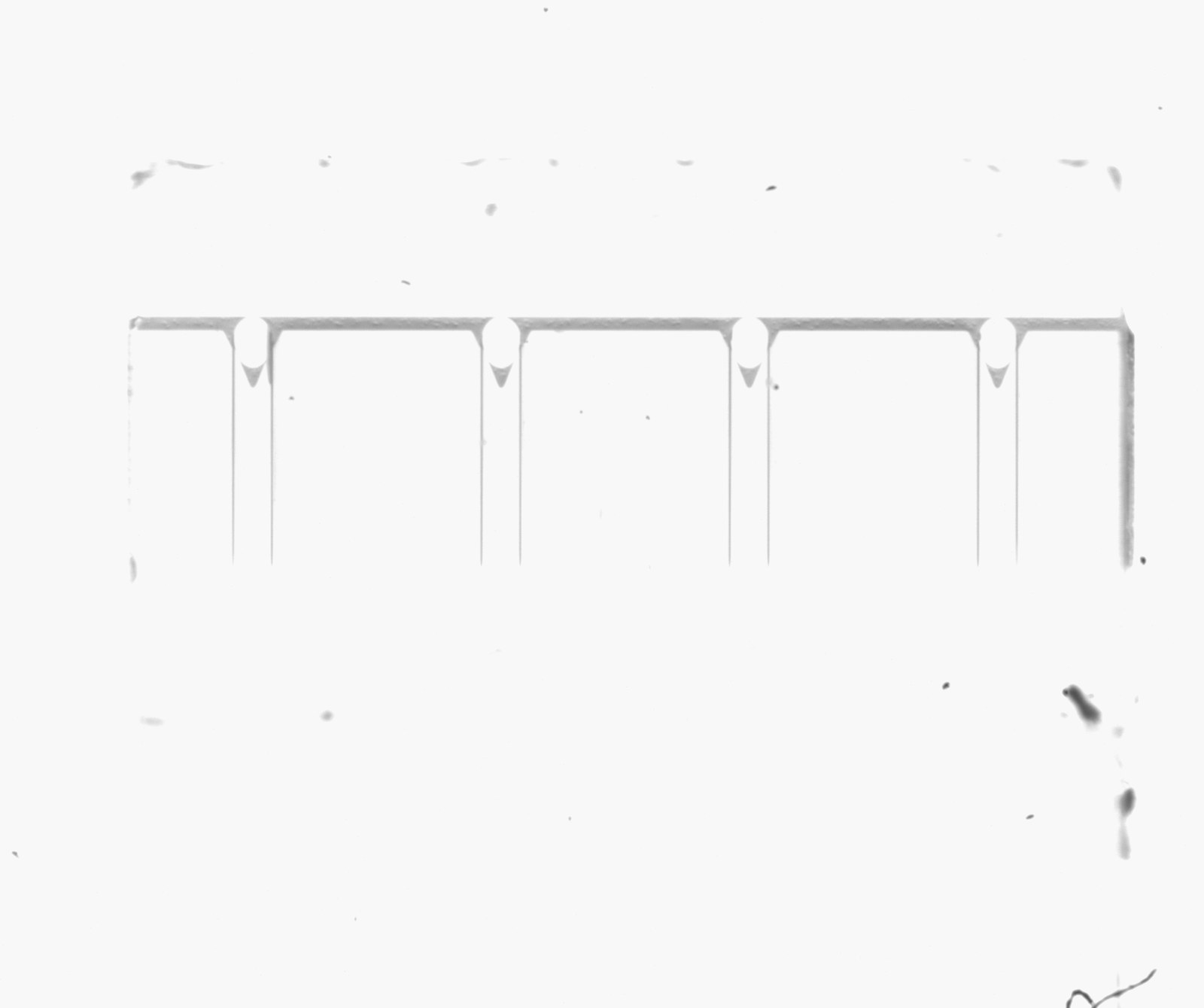
The fourth image is a different aspect of the same part family: the V-groove substrate seen from the side, with the row of groove rails and their U-shaped bottoms resolved along the top edge. Side or oblique views like this are used to check groove depth, rail edge chipping and the overall substrate edge condition — a reminder that "V-groove inspection" is not only an end-face job; the groove geometry that positions the fibers is judged on its own.
7. Illumination Notes
- Coaxial for the fiber ends. Polished fiber ends return light along the axis; coaxial epi-illumination through the lens's built-in splitter makes them bright against the darker substrate.
- Low-angle or ring light for the substrate and grooves. Edge chipping, glue marks and groove shadows read better with grazing light that the coaxial path deliberately avoids.
- Wavelength matters less than geometry here, but the white/yellow/blue trade-offs for end faces are compared in our dedicated end-face lighting selection guide.
FAQ
How is V-groove / FAU inspection different from single connector end-face inspection?
A connector end face is one target with a fixed position; a V-groove substrate is a row of small targets on a larger, mixed-reflectivity body. The inspection therefore runs at two scales — an array overview to confirm every fiber is present, seated and clean, and a detail view on single fiber ends for concentricity and contamination judgments. Connector-style high magnification alone is inefficient for the overview.
Which lens type fits the array overview?
A telecentric lens with built-in coaxial illumination. Telecentricity keeps the pitch between adjacent fiber ends free of perspective distortion, and the coaxial path reaches into the shallow grooves so the polished fiber ends return bright, high-contrast images. Standard FA lenses can work at lower demands, but pitch accuracy and groove contrast are weaker.
How is total magnification calculated when a zoom lens is converted to an APO objective?
Total magnification = zoom magnification × APO objective magnification × 0.55, where 0.55 is the mandatory coupling factor of the APO adapter ring. For example, a 4.5X zoom on a 5X APO objective gives about 12.4X (estimated). Skipping the 0.55 factor overstates magnification by nearly half and corrupts the field-of-view and pixel-size calculations built on it.
Which illumination is best for fiber ends seated in V-grooves?
Coaxial epi-illumination for the fiber ends themselves — the polished ends return light along the axis while the substrate does not. For substrate-edge and groove-wall defects, add a low-angle or ring light. The geometry of the light, not its color, is the primary lever on V-groove samples.
What defects should be checked on an FAU end face?
The standard checklist: missing or crossed fibers, fiber end protrusion or recession relative to the substrate, core/cladding concentricity, end-face contamination (dust, lint, polish residue, adhesive bleed), and chips or scratches on the substrate end face and groove rails.
Can one station cover both the array overview and the single-fiber detail?
Yes — a continuous-zoom lens with a coaxial port, converted through an APO adapter ring to an APO objective, sweeps from overview to detail on one camera. The total magnification is zoom × objective × 0.55. Where the highest resolution on one fiber end is required, a dedicated microscope-optics station remains the stronger option.
Further Reading
- Fiber End-Face Inspection Lighting: White vs Yellow vs Blue Compared
- Fiber Connector End-Face Inspection Case: Zoom Lens + 5X APO Objective
- High-Magnification Fiber End-Face Inspection with a 10X Telecentric Lens
- Wedge Lens for Fiber Optic Inspection
- Telecentric Lens FOV, WD & Magnification Formulas
POMEAS can bench-test your actual V-groove or FAU sample with telecentric, zoom+APO or microscope optics and recommend the imaging and illumination combination that fits your defects list. Submit your requirement through the contact page with sample images and the pitch / fiber count of your array.

Subscribe to Our Newsletter
Simply enter your email to receive the latest news and insights from Pomeas. Stay connected with Pomeas and be the first to discover new innovations in optical excellence.


