High-Magnification Fiber End-Face Inspection with a 10× Telecentric Lens
A fiber end face can occupy only a small part of the camera image, while dust, surface texture and reflections compete for contrast around it. This article uses real monochrome images to show what a 10× bi-telecentric coaxial lens can bring to fiber-array inspection—and where the limits still need to be checked.
What made this sample difficult to inspect?
When we looked at the original images, the first thing we noticed was not a perfectly clean background. It was the opposite: the field contained a large amount of texture and many bright circular features. The five fiber end faces were visible, but they were not isolated from everything around them.
This is a common problem in practical fiber inspection. Magnification alone does not solve it. The optical system must keep the end-face geometry stable, while the lighting has to produce enough contrast to separate the area of interest from the surrounding surface.
Why use a 10× bi-telecentric lens?
The lens used for this configuration is the POMEAS LTCM10-65C. It is a fixed 10× bi-telecentric lens with a coaxial illumination port. The telecentric design helps reduce the apparent size change caused by small position variations along the optical axis. This is useful when the task includes edge location, spacing or dimensional comparison.
The lens has a 65 mm object-side working distance and supports sensors up to 1.1 inch. Its nominal object-side resolution is 1.86 μm and its object-side NA is 0.18.
These values describe the lens. They are not, by themselves, a guarantee that a complete inspection system will measure to 1.86 μm or reliably detect every defect of that size.
| Item | LTCM10-65C Specification |
|---|---|
| Optical design | Bi-telecentric lens |
| Magnification | 10.00× |
| Object-side working distance | 65.00 mm |
| Maximum image circle | 18.4 mm, suitable for sensors up to 1.1 inch |
| Maximum circular object field | Φ1.84 mm |
| Object-side depth of field | 0.02 mm |
| Image-side best F/# | 27.78 |
| Image-side MTF30 | 35 lp/mm |
| Object-side resolution | 1.86 μm |
| Object-side telecentricity | <0.1° |
| Image-side distortion | <0.1% |
| Object-side NA | 0.18 |
| Camera mount | C-Mount |
| Coaxial illumination | Supported |
Field of view depends on the camera sensor
The same 10× lens produces a different rectangular field of view when it is paired with a different sensor size. Before selecting the camera, check whether the complete fiber array must fit in one frame or whether the task only needs a closer view of one end face.
| Camera Sensor | Sensor Area | Object-Side FOV |
|---|---|---|
| 2/3 inch | 8.4 × 7.1 mm | 0.84 × 0.71 mm |
| 1 inch | 13.13 × 8.76 mm | 1.31 × 0.88 mm |
| 1.1 inch | 14.19 × 10.3 mm | 1.42 × 1.03 mm |
What changed between the real images?
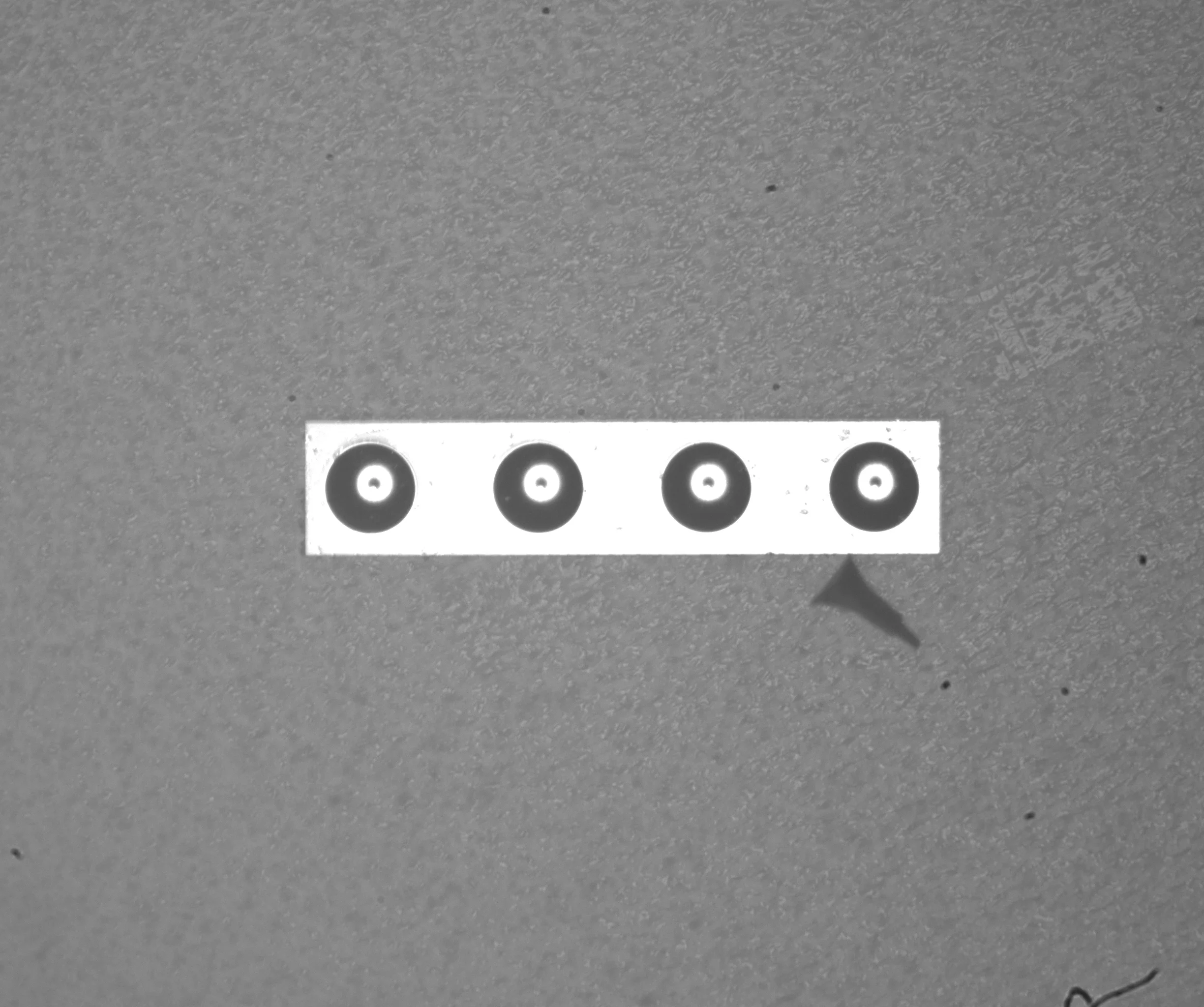
The following images show the same type of sample under different imaging conditions. The circular end faces remain visible, but the balance between the end-face interior, its outer edge and the surrounding surface changes noticeably.
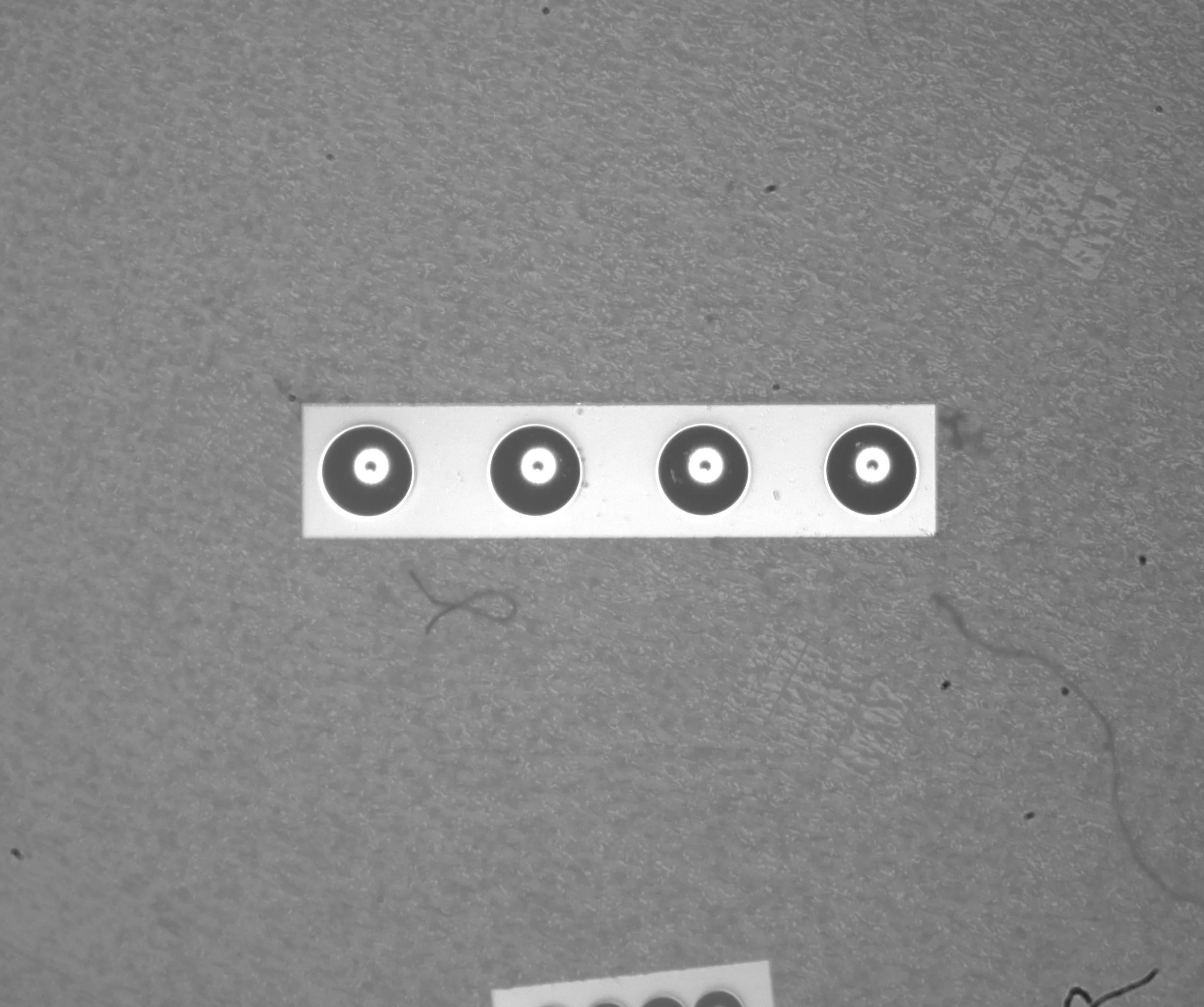
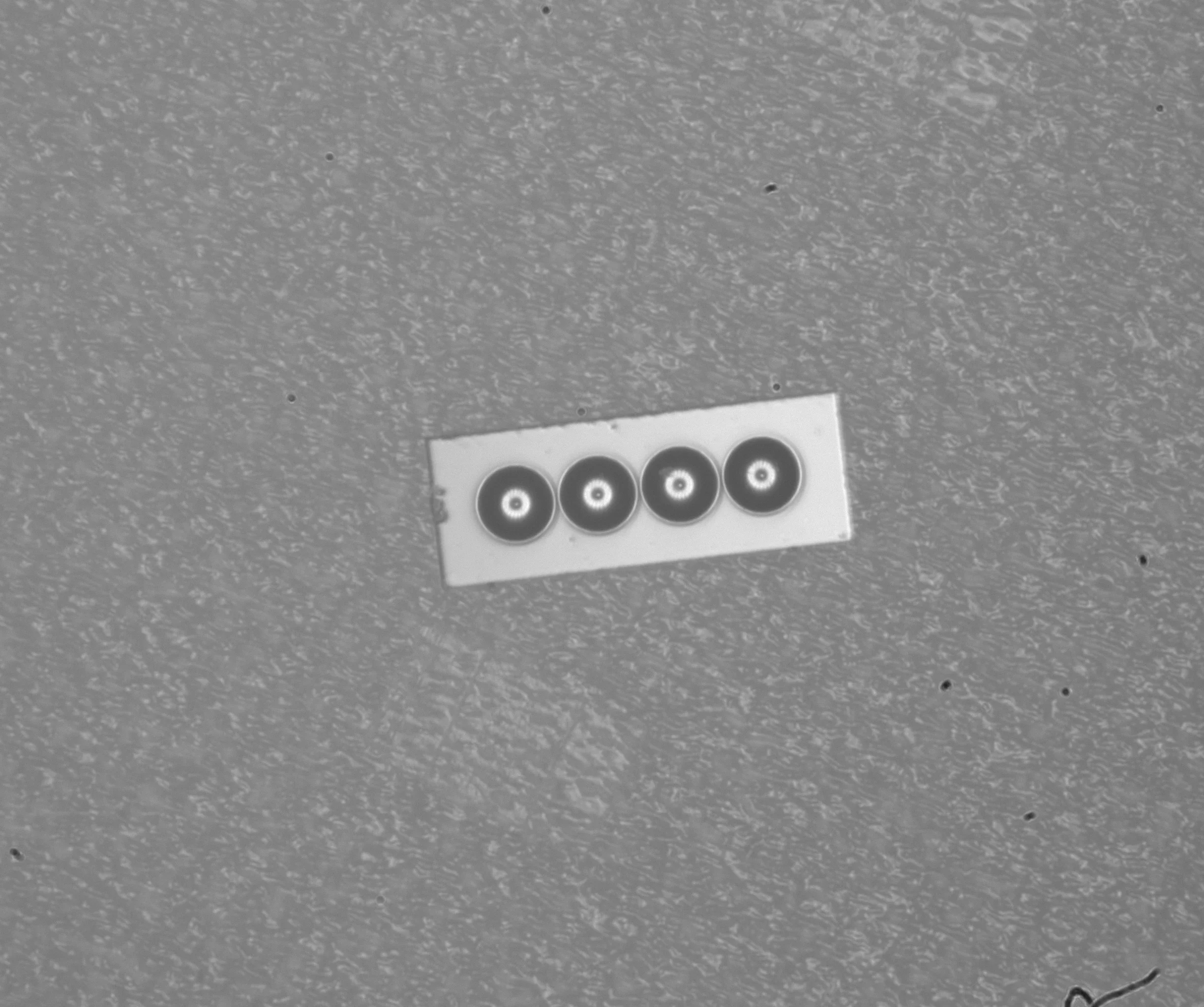
One image is not automatically “better” than the other. The correct condition depends on what must be inspected. Edge measurement, surface observation and automated defect classification may each require a different exposure or illumination balance.
Coaxial illumination is useful, but setup still matters
Coaxial illumination sends light through the optical path toward the sample. On a relatively flat reflective surface, it can produce a clearer difference between the end face and the surrounding region. The LTCM10-65C includes a coaxial illumination port, so the light source can be integrated directly with the lens.
In practice, three adjustments still matter:
- Sample angle: A small tilt can change the returned light and make one side of an end face brighter than the other.
- Exposure: Excessive brightness can hide edge detail, while low exposure can bury small features in the background.
- Focus position: The stated object-side depth of field is only 0.02 mm, so mechanical positioning and focus stability cannot be treated casually.
A practical inspection workflow
- Confirm the fiber or fiber-array dimensions and decide whether the entire array must fit in one image.
- Select the camera sensor and pixel size according to the required field of view and smallest feature of interest.
- Fix the sample at a repeatable angle and set the lens at its 65 mm working distance.
- Adjust coaxial illumination and exposure until the target edge or surface feature is stable, rather than simply making the image as bright as possible.
- Calibrate the complete camera-lens system before using the image for dimensional evaluation.
- Test good and unacceptable samples to establish a real detection threshold and repeatability result.
What this configuration is suitable for
Suitable Tasks
- High-magnification fiber end-face imaging
- Fiber Array and V-Groove assembly observation
- MPO/MTP, FAU and fiber-component visual checks
- End-face edge and spacing evaluation
- Machine-vision integration using fixed magnification
Needs Additional Equipment or Verification
- Three-dimensional surface-angle measurement
- Surface roughness or interferometric measurement
- Return loss, coupling efficiency or wavefront testing
- Automatic defect classification without defined criteria
- Guaranteed accuracy based only on lens resolution
Frequently Asked Questions
Does 1.86 μm object-side resolution mean 1.86 μm measurement accuracy?
No. It is a nominal optical-resolution specification for the lens. System accuracy also depends on the camera pixel size, image contrast, calibration, mechanics, lighting, software and repeatability.
Can a 2/3-inch camera be used with this lens?
Yes. With the listed 8.4 × 7.1 mm sensor area, the corresponding object-side field is approximately 0.84 × 0.71 mm. A larger sensor provides a larger field while the lens magnification remains 10×.
Why is the depth of field only 0.02 mm?
High magnification and NA 0.18 provide fine optical detail, but they also make focus more sensitive. The sample position and lens mounting therefore require good mechanical stability.
Can the lens inspect scratches and contamination?
It can provide high-magnification images of surface features, but the actual detectable size and classification reliability must be established with the selected camera, lighting, software and representative samples.
Is this lens suitable for dimensional measurement?
The telecentric design is helpful for stable edge imaging and dimensional evaluation. The complete system still requires calibration and repeatability testing against the required tolerance.
Related Fiber and Lens Resources
Send Us the Sample and Inspection Requirement
For lens and camera selection, please provide the fiber type, array dimensions, required field of view, smallest feature or tolerance, available working distance, inspection speed and sample images. POMEAS can then evaluate whether a fixed 10× telecentric setup is appropriate or whether another magnification and imaging structure would be a better fit.
Discuss Your Inspection Requirement


