Knowledge
Fiber Connector End-Face Inspection Case: Zoom Lens with 5X APO Objective and Yellow Coaxial Light
This article documents a delivered fiber end-face inspection project: a fiber connector manufacturer needed to image connector end faces inside a confined installation space, with two hard requirements — the bright white inspection regions on the end face must be visible with their complete contour, and the illumination had to be yellow light as specified by the customer's process. The final configuration combines a 0.7–4.5X zoom lens, a 5X APO objective, an APO adapter ring and a yellow point light source, with a measured working distance of 65 mm. Below we publish the full configuration, the magnification conversion formula, the assembly dimensions and the on-site imaging result, so that engineers with similar requirements can benchmark their own selection directly.
Other languages: 中文 · Español · Français · Русский · العربية
1. The Requirement and Three Practical Difficulties
The target is the end face of a fiber optic connector. In the sample photograph provided by the customer, the critical inspection zone near the end face is marked with a red circle. The requirement on site was twofold: see the overall contour of the end face, and present the white inspection regions on it completely, as the basis for subsequent manual judgment.
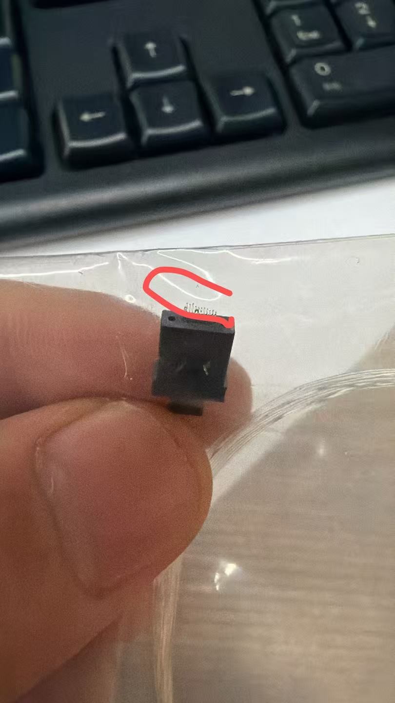
The requirement sounds routine, but delivering it meant clearing three hurdles at once:
Difficulty 1: insufficient magnification. With a standard zoom lens (0.7–4.5X) alone, the contour details of the white regions on the end face were too small. The customer wanted an additional stage of objective magnification stacked on top, so that the inspection regions fill the frame.
Difficulty 2: constrained working distance and installation space. Once an objective is added, enough clearance must be kept between the front of the lens and the workpiece for handling. Meanwhile the mounting position on the production line was already fixed: how long the barrel is, what clamp diameter it offers, and from which direction the light source enters — all of this had to be confirmed before purchase to avoid rework.
Difficulty 3: illumination. The customer's process explicitly required yellow light. An end face is a small, highly reflective target, so the illumination had to travel through a coaxial epi-illumination path — light injected sideways, split inside the lens, and sent down the optical axis onto the end face. Without coaxial geometry, the contrast between the white regions and the surrounding end face simply does not appear.
2. The Optical Configuration: Four Components, Four Jobs
The delivered configuration is as follows, with each component carrying exactly one responsibility:
| Component | Model / Spec | Role in the system |
|---|---|---|
| C-mount tube | 63010 (1X) | Provides the camera-side C-Mount interface and 1X relay |
| Zoom lens | 63106 (PMS-LZ-63106D6, 0.7–4.5X, 2/3″ sensor, coaxial port) | Continuous-zoom body with built-in coaxial beam-splitter path |
| APO adapter ring | 65000 | The interface between the zoom lens and the APO objective |
| APO objective | 5X | Front-stage magnification; sets the working distance |
| Illumination | Point light source (yellow) | Injected sideways into the coaxial path |
A few notes:
- 63106 is the PMS-LZ-63106D6: a 0.7–4.5X manual zoom lens for 2/3″ sensors with a built-in coaxial epi-illumination port. We chose it over the higher-magnification 6.5X model because, once the 5X APO objective is stacked, the total magnification is already sufficient — redundant magnification only costs working distance and depth of field.
- The APO objective is apochromatic and flat-field corrected, which on a small flat target like an end face keeps both magnification accuracy and color consistency under control.
- The yellow point light source enters through the Φ25 sideways light port on the barrel, so it occupies none of the front working space.
3. How to Calculate Total Magnification: Do Not Skip the 0.55 Factor
This is the most commonly miscalculated step in any zoom-lens-plus-APO-objective build. Many estimators simply multiply "zoom magnification × objective magnification". But when a zoom lens is directly converted to an APO objective through an APO adapter ring, the system must include a conversion factor of 0.55:
Total magnification = zoom magnification × APO objective magnification × 0.55
For this case: 4.5 × 5 × 0.55 = 12.375, i.e. a maximum total magnification of about 12.4X (estimated value, per the technical conversion).
Two practical consequences:
- Turning the zoom ring sweeps the total magnification continuously from about 1.9X (0.7 × 5 × 0.55) up to 12.4X, letting the customer cover both "overview" and "detail" at a single station.
- If you back-calculate field of view and sensor pixel matching from 22.5X (skipping the 0.55 factor), the whole selection drifts off target. This is exactly why we recommend confirming magnification against a live image first, then fixing camera parameters.
4. Installation Space and Working Distance: 3D Model First, Then the Line
To lock down the installation questions before purchase, we delivered a STEP 3D model of the complete optical path together with a 2D dimensioned drawing. With the 3D model, the customer ran interference checks directly inside their line layout and verified the installation space and working distance in advance.
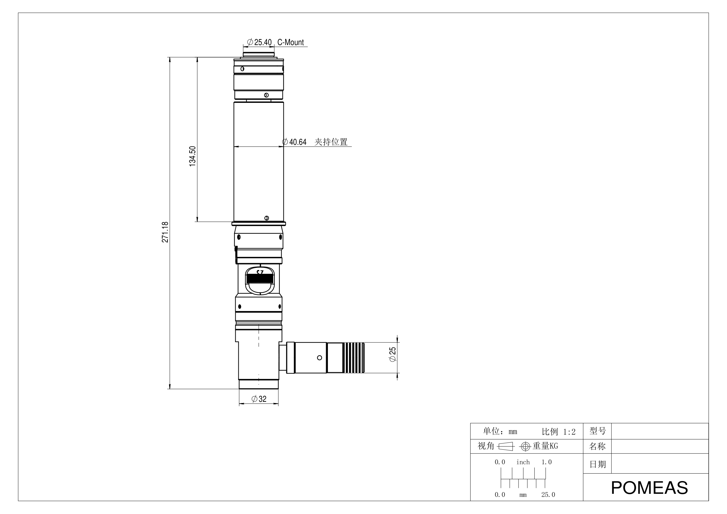
Key drawing dimensions (in mm):
- Overall assembly length 271.18 (from the C-Mount reference face to the front of the optics)
- C-Mount interface Φ25.40
- Clamp location Φ40.64, located 134.50 from the C-Mount reference face
- Barrel front section Φ32
- Sideways point-light-source port Φ25
Among these, "clamp location Φ40.64 at 134.50 from the C-mount" delivered the most value for the customer: the fixture only needs to grip the barrel at this one location, and the diameter changes before and after it do not affect clamping.
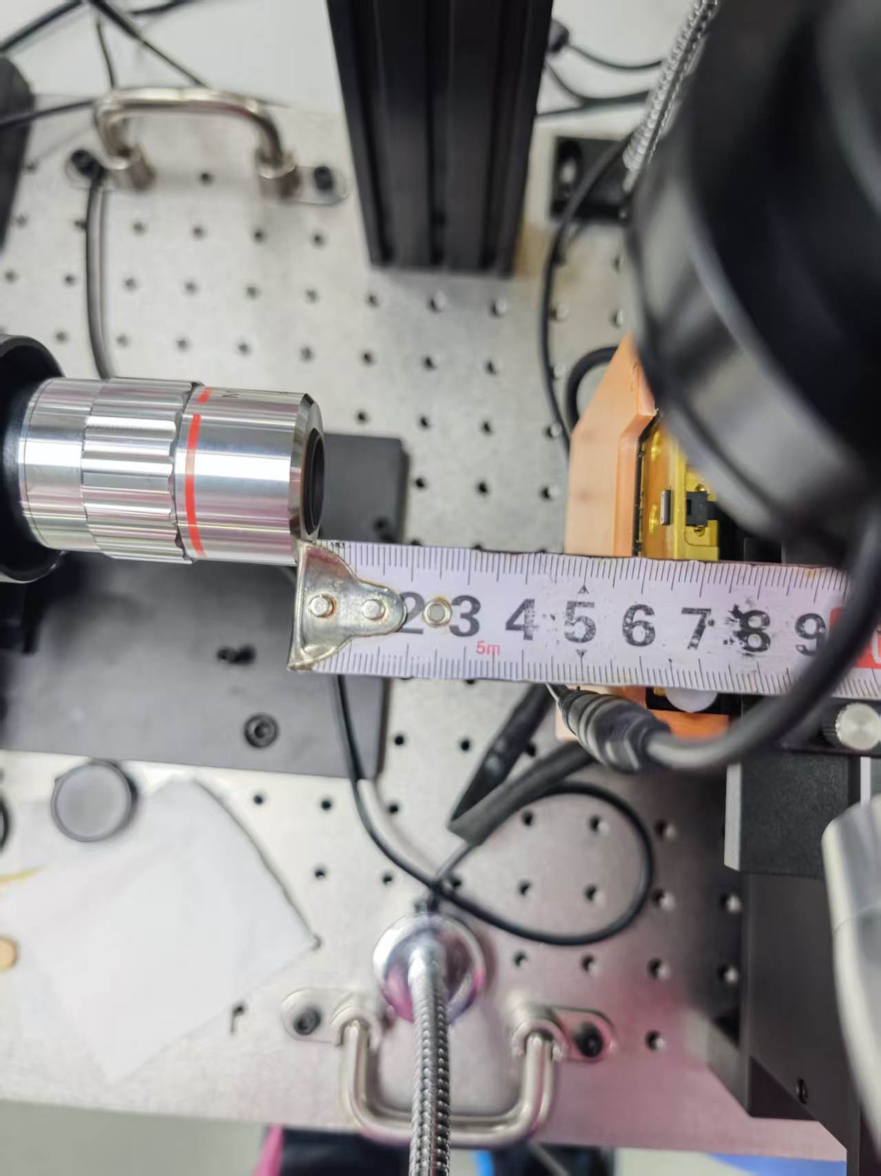
Measured on the machine after installation: the working distance from the front of the APO objective to the workpiece is about 65 mm. That is enough room for the customer's fixture and part-loading motions, with focus travel to spare.
5. Illumination: End-Face Imaging Under Yellow Coaxial Light
Per the customer's process requirement, the illumination uses a standard yellow point light source. Light is injected through the sideways port, split inside the zoom lens, and sent down the imaging axis onto the end face. The advantage of this "beam-splitter inside the lens, light source sideways" architecture is that the source occupies no front working space, and height variations on the end face do not produce shadow displacement.
White-light imaging was also compared on site; the final choice of yellow light followed the customer's process specification. For the wavelength-level differences between white, yellow and blue light in fiber end-face inspection, see our dedicated selection guide listed under further reading.
The actual imaging result under yellow coaxial illumination is shown below (cropped from a live screen capture): three end-face regions are visible simultaneously in one field of view. The center end face is in focus, and the contour of its two white inspection regions is complete and clear — directly usable as the manual-judgment image.
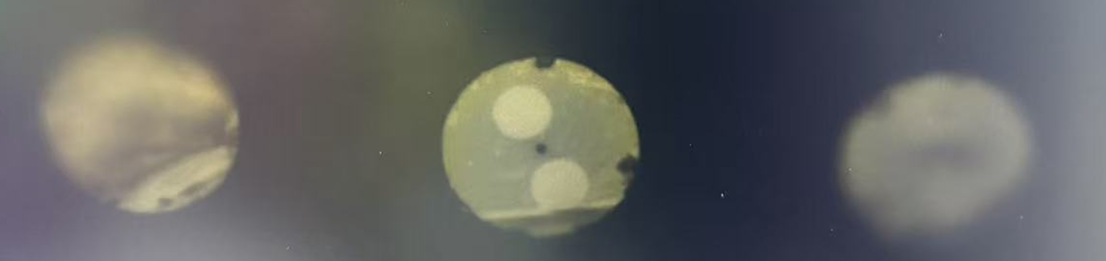
This single frame confirms two things: the ~12.4X total magnification brings the end face to a comfortable observation scale, and under coaxial yellow light the contrast between the white regions and the end-face substrate meets the customer's judgment requirement.
6. Transferable Selection Takeaways
Five reusable lessons from this delivery:
- Apply the 0.55 factor first. Zoom lens to APO objective through the adapter ring: total magnification = zoom × objective × 0.55. Never back-calculate FOV from a 22.5X figure that skips it.
- Lead with the 3D model. Run interference checks with the STEP model and 2D drawing before purchase; the 271.18 mm overall length, Φ40.64 clamp and Φ25 side light port go into the line layout first.
- Clamp at Φ40.64. The clamp face at 134.50 mm from the C-mount is the mechanical datum for this optical path.
- Coaxial illumination through the side port. For end-face inspection, prefer the lens's built-in beam-splitter coaxial path with the source entering the Φ25 side port — it consumes no working distance.
- Verify magnification and illumination together, on live images. The acceptance criterion in this case was concrete: the complete contour of the white inspection regions must be visible.
FAQ
How do you calculate total magnification when a zoom lens is converted to an APO objective?
Per the technical conversion: total magnification = zoom magnification × APO objective magnification × 0.55, where 0.55 is the mandatory conversion factor when the zoom lens is directly converted to an APO objective through the APO adapter ring. In this case 4.5 × 5 × 0.55 ≈ 12.4X (estimated). Skipping the factor skews the entire field-of-view and pixel-matching calculation.
What is the working distance of this configuration?
Measured on site: about 65 mm from the front of the APO objective to the workpiece surface, enough for fixture and part-handling clearance plus focus travel. If your fixture is taller or shorter, the working distance can be adapted at selection time by choosing an APO objective with a different magnification/WD specification.
Why yellow light for fiber end-face inspection?
In this case yellow light was specified by the customer's process. Combined with the zoom lens's built-in coaxial splitter, the contour of the white inspection regions on the end face came out complete and clear, meeting the judgment requirement. For how white, yellow and blue light differ on end faces, see our article "Fiber End-Face Inspection Lighting: White vs Yellow vs Blue".
How can installation space be confirmed before purchase?
We deliver a STEP 3D model plus a 2D dimensioned drawing with the proposal. Key dimensions in this case: overall length 271.18 mm, C-Mount Φ25.40, clamp Φ40.64 (134.50 mm from the C-mount), front section Φ32, side light port Φ25. With the 3D model you can run interference checks directly in your line layout.
How many end faces fit in one field of view?
In the delivered setup, three end-face regions are visible simultaneously in one field of view, with the center one in focus. The actual number depends on end-face pitch and camera sensor size — we recommend a sample test with your actual end-face spacing.
What kind of lens is the 63106?
The 63106 (PMS-LZ-63106D6) is a 0.7–4.5X manual zoom lens for 2/3″ sensors, with a built-in coaxial epi-illumination path and a sideways light port — well suited to magnified inspection of small reflective targets such as end faces, chips and scratches.
Further Reading
- Fiber End-Face Inspection Lighting: White vs Yellow vs Blue Compared
- Industrial Lens Vignetting: 3 Causes and Fixes
- Telecentric Lens FOV, WD & Magnification Formulas
- Microscope 400X vs Machine Vision Zoom Lens: Magnification Conversion
- Coaxial Illumination for Reflective Metal: 3 Surface Types, 7 Steps
POMEAS can evaluate the optics, illumination and fixture setup from your actual sample and inspection requirement. Submit your requirement through the contact page with sample images, the size range and the required accuracy.

Subscribe to Our Newsletter
Simply enter your email to receive the latest news and insights from Pomeas. Stay connected with Pomeas and be the first to discover new innovations in optical excellence.


