Knowledge
Transparent and Coated Surfaces: Zoom Lens Inspection Setup
Transparent and coated parts break the assumption that most vision setups rely on: that the feature you want to see reflects light differently from its surroundings. A clear glass edge, a thin film on a wafer, an anti-reflective coating on a lens or a transparent blister pack all produce images where the part and the background can have almost the same brightness. Magnification does not fix this, and neither does a better camera. What fixes it is choosing illumination and geometry so that the feature creates a contrast difference at all. This article sets out what a zoom lens can and cannot do for these parts, and how to configure the illumination around it.
Why transparent parts are a contrast problem, not a resolution problem
An opaque part scatters or absorbs light at its edges, so an edge is a brightness transition. A transparent part transmits most of the light through it, so at an edge the only signal is refraction and reflection at the boundary — a thin bright or dark line, often a few micrometres wide, whose visibility depends on the angle between the illumination, the surface and the camera. Increase magnification and the line is drawn larger, but it does not become easier to distinguish from the noise; if the illumination angle was wrong, a bigger image of a low-contrast edge is still a low-contrast edge.
The practical consequence is that transparent-part inspection is specified from the illumination backwards. Decide what optical effect marks the feature — a specular highlight, a dark-field scatter, an interference fringe, a polarisation change — then choose the lens that can carry that illumination and still give the field you need.
The two-surface problem, and what depth of field does to it
A transparent plate has a top surface and a bottom surface, and both reflect. With axial illumination the two reflections travel back along the same path and can arrive at the sensor simultaneously, producing a double image or a ghost. Whether they separate depends on depth of field and on the optical thickness of the part.
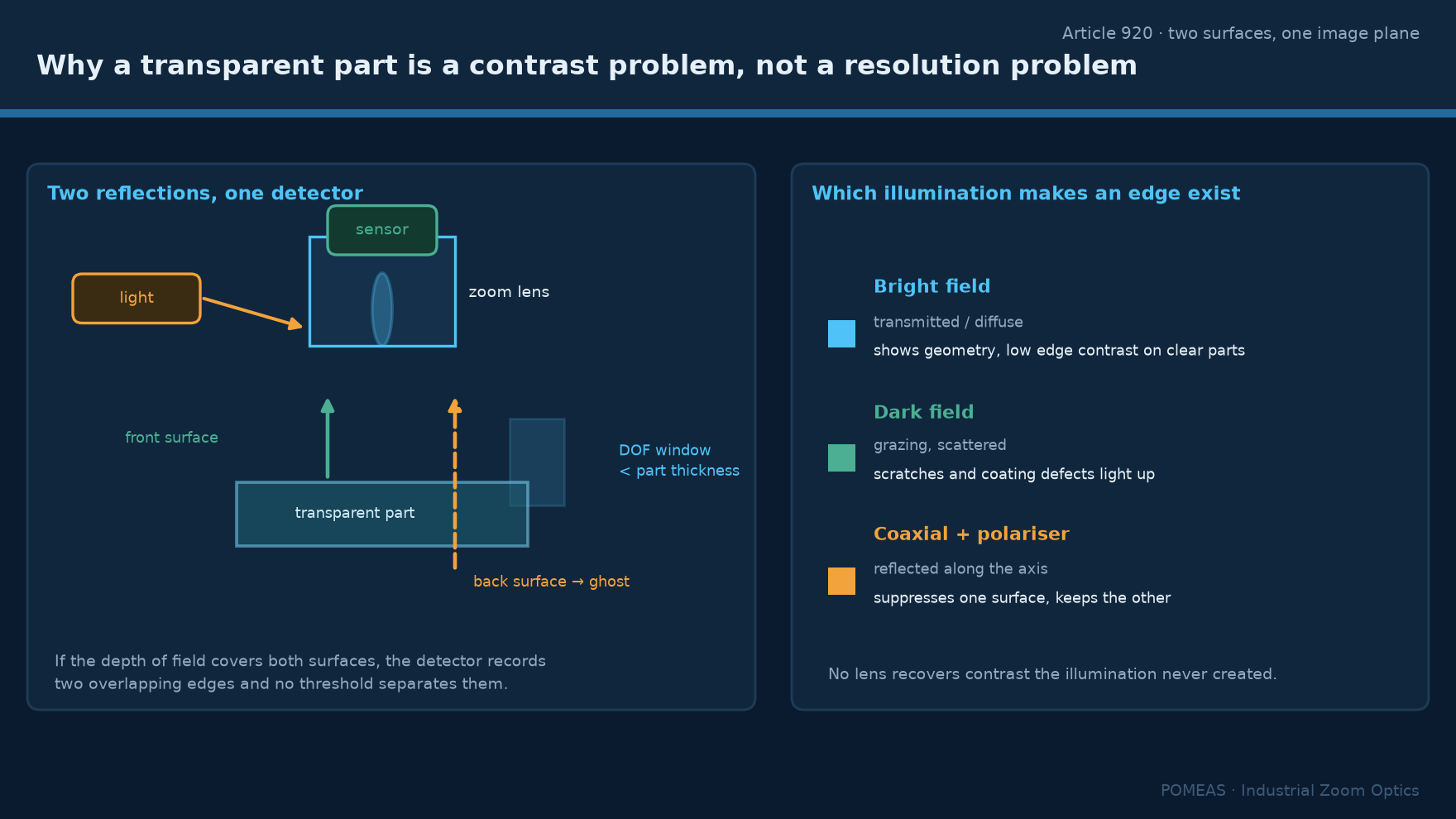
Consider a 1 mm glass plate with a refractive index around 1.5: its optical thickness is roughly 1.5 mm, so the two surfaces are about 1.5 mm apart in image space. At 0.58× in the POMEAS 12.5× family the depth of field is 2.75 mm, which means both surfaces are inside it and both appear sharp. At 7.5× the depth of field is 0.056 mm, so only one surface can be in focus and the other becomes a defocused ghost spread over the field. Neither state is wrong; they answer different questions. Low magnification shows both surfaces at once, which is what you want for a bubble or a chip that could be on either face. High magnification isolates one surface, which is what you want for a coating defect.
| Task | Magnification band | Why |
|---|---|---|
| Bubble, inclusion, chip anywhere in the part | 0.58× to 2× | DOF 2.75 mm to 0.27 mm keeps both surfaces usable |
| Coating defect on one face | 3× to 7.5× | DOF 0.15 mm to 0.056 mm isolates one surface |
| Edge chip, chamfer, dimensional feature | 1× to 3× | Field contains the edge and its reference |
| Film thickness uniformity | Not a zoom lens task | Requires interferometry or spectral reflectance |
The last row matters. Film thickness is a measurement of optical path difference, and a zoom lens forms an image; it does not measure path difference. Claiming thickness capability from a zoom lens image would be an overstatement regardless of magnification.
Illumination choices and what each one reveals
Coaxial illumination. Light travels down the optical axis and returns along it. On a flat, reflective surface this gives an even, bright field and shows coating non-uniformity as brightness variation. On a transparent part it produces the double reflection described above, and on a coated part with a wavelength-dependent reflectance it can produce a colour shift that looks like a defect but is a coating property. Coaxial is the right default for coated metal and the wrong default for bare glass.
Dark field. Light arrives at a steep angle and only scattered light reaches the camera, so the background is dark and edges, scratches and particles are bright. For a transparent part this is often the only configuration that makes an edge visible, because the edge scatters while the bulk transmits. The trade is that dark field is sensitive to surface texture and will show every dust particle, which may or may not be what the inspection is about.
Backlight. The part is silhouetted, which makes transparent parts behave like opaque ones. This is the most reliable way to measure an outer dimension or detect a hole in a transparent moulding, because the geometry, not the surface, creates the contrast. It requires the part to be held clear of the light source, which is a fixture constraint.
Polarised light. Crossed polarisers suppress specular reflection from the surface and reveal stress birefringence inside a transparent part. For moulded transparent components this shows moulded-in stress as coloured bands, which is a real defect signal and not obtainable any other way.
Where the zoom range actually helps
Two situations. First, when the same part must be checked for a bulk defect and a surface defect: the wide end finds the bulk defect and the narrow end characterises it, without moving the part. Second, when incoming parts vary in size and a fixed lens would either crop the large ones or waste resolution on the small ones.
The POMEAS 12.5× family covers 0.58× to 7.5× at 77.4 ± 2 mm working distance, giving a 2/3-inch sensor a field from 15.17 mm down to 1.17 mm wide. At the wide end a 15 mm window is enough for a lens element; at the narrow end 1.17 mm is enough to characterise a coating pit. The working distance stays the same across the range, which matters because changing working distance would change the illumination geometry and therefore the contrast.
That last point is worth stating separately: in transparent-part inspection the illumination is part of the measurement, so a lens that holds working distance constant across its zoom range is worth more than one that does not. The real working-distance values across the product families are tabulated in zoom lens working distance: nine real WD values.
What the optics cannot do
A zoom lens cannot measure film thickness, cannot see through a coating to a buried layer, and cannot create contrast where the feature and its background have the same optical properties under every available illumination. It also cannot separate two reflections that are closer together than its depth of field: if a 0.1 mm film is being inspected at 0.58×, the two surface reflections overlap completely and no zoom setting will pull them apart at that magnification.
A related limit is numerical aperture. At 0.58× the 12.5× series has NA 0.025, which is low, so the lens collects little scattered light. Dark-field and low-light techniques therefore need brighter sources or longer exposures than they would with a high-NA objective. The relationship between NA, resolution and light collection is set out in magnification is not resolution.
A configuration checklist
Decide whether the defect is on a surface or in the bulk. If surface, pick coaxial for coated reflective parts and dark field for bare transparent parts. If bulk, pick backlight for geometry and crossed polarisers for stress. Then set the magnification from the field the bulk defect needs, not from the surface defect, because the bulk view is the wider one. Confirm depth of field at that magnification against the part thickness. Confirm the working distance leaves room for the illumination hardware, remembering that a ring light occupies 20 mm to 40 mm in front of the lens.
Then verify on a real sample with a known defect before quoting a specification. Transparent-part inspection fails more often at the illumination stage than at the lens stage, and a sample test costs an hour while a wrong installation costs a project.
Frequently asked questions
Can a zoom lens detect a coating defect on glass?
It can image one, if the illumination creates contrast. Coaxial light shows coating non-uniformity as brightness variation on a reflective coating; on an anti-reflective coating the signal is weaker and dark field or oblique light often works better. The lens sets the field and resolution, not the contrast.
Why do I see two images of the same edge?
Because the top and bottom surfaces of a transparent part both reflect, and both are inside the depth of field at low magnification. At 0.58× in the 12.5× family the depth of field is 2.75 mm, which is more than the optical thickness of most cover glasses. Raising magnification to 3× or above separates them.
Can I measure glass thickness with this setup?
No. Separating two surface reflections in an image is not a thickness measurement; it is an observation of two focus positions at best. Thickness requires a confocal or interferometric sensor, or a contact gauge.
What illumination works for a transparent blister pack?
Backlight, because it converts the transparent part into a silhouette and makes the seal geometry and any hole visible. Coaxial illumination on a clear blister produces a bright, low-contrast image with strong ghosting from the two surfaces.
Does a coaxial lens help with transparent parts?
Only for coated or partially reflective surfaces. On bare glass, coaxial light produces the double reflection and a washed-out image. Its real value is on flat reflective metal and on coated optics, where it gives even illumination across the field.
Why is the image dim at high magnification on a transparent part?
Two reasons: the effective f-number rises with magnification, and a transparent part transmits most of the light rather than returning it. Expect to need either a brighter source or a longer exposure, and expect dark-field configurations to be the dimmest of all.

Subscribe to Our Newsletter
Simply enter your email to receive the latest news and insights from Pomeas. Stay connected with Pomeas and be the first to discover new innovations in optical excellence.


