Knowledge
How to Choose a Telecentric Lens: Magnification, FOV, Working Distance, Depth of Field & Measurement Accuracy
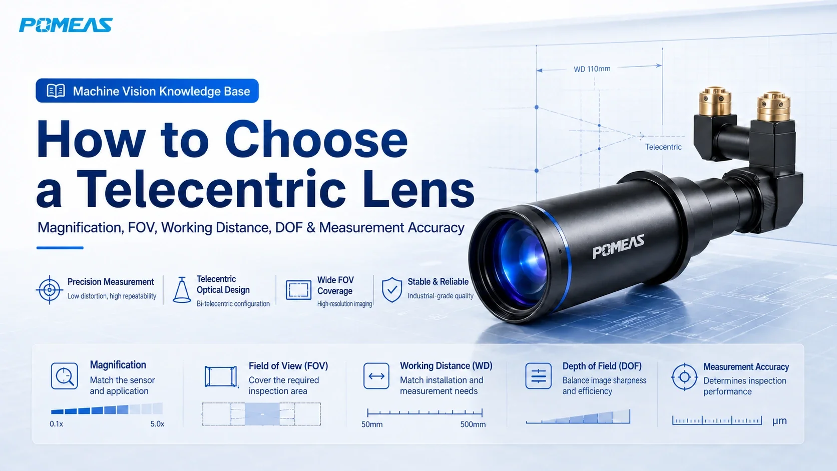
1. Quick Answer: Do Not Select a Telecentric Lens by Magnification Alone
Quick answer: A proper telecentric lens selection normally starts with the camera's effective sensor size, required field of view (FOV), and working distance (WD). These parameters are used to estimate the required optical magnification. You should then verify depth of field (DOF), workpiece height variation, lens resolution, distortion, telecentricity, illumination method, and available installation space.
At POMEAS, we often receive questions such as, “Do you have a 0.5X telecentric lens?” or “I need a 1X telecentric lens.”
Magnification is important, but magnification alone is not enough to determine the correct lens. For example, the same 1X telecentric lens will provide different fields of view when paired with a 2/3-inch, 1-inch, or 1.1-inch camera sensor.
The reverse is also true. If an application requires a 20 mm field of view but the effective camera sensor dimensions are unknown, the required magnification cannot be determined accurately from the FOV alone.
Therefore, before deciding whether you need a 0.5X, 1X, or 2X telecentric lens, confirm the following:
- What are the actual effective dimensions of the camera sensor?
- What field of view must be covered?
- How much working distance is available between the lens and the workpiece?
- Does the workpiece have height variation or positioning variation?
- Which dimensions need to be measured, and what are the required accuracy and repeatability?
- Are you measuring an external silhouette or inspecting surface features?
- What type of illumination can be installed in the system?
If you are still determining whether a telecentric lens or a conventional FA lens is more suitable, you can first review the available POMEAS machine vision lens solutions. This guide focuses on how to select the correct model once a telecentric optical system has been identified as the appropriate solution.
2. Which Applications Are Better Suited to Telecentric Lenses?
The primary purpose of a telecentric lens is not simply to produce a sharp image. Its key advantage is the ability to reduce perspective error and minimize magnification variation caused by object displacement, helping dimensional measurements remain more stable.
A conventional machine vision lens uses perspective imaging. When a workpiece moves closer to the lens, its image generally becomes larger; when it moves farther away, its image generally becomes smaller. For barcode reading, OCR, presence inspection, and general visual inspection, this effect may not be critical.
However, when the system measures hole diameters, spacing, edge positions, or precision profiles, even a small change in object height can introduce dimensional variation. This is where telecentric imaging becomes particularly valuable.
Typical applications include:
- Outer diameter, inner diameter, and hole diameter measurement
- Pitch, slot width, and gap measurement
- Edge position and profile measurement
- Precision metal component inspection
- PCB pad and electronic component measurement
- Semiconductor, connector, and terminal inspection
- Smartphone frame, glass, and display dimensional inspection
- Dimensional measurement of parts with height variation
- Machine vision applications requiring low distortion and high measurement repeatability
If the application only requires barcode reading, character recognition, presence/absence inspection, or general positioning, a telecentric lens may not be the most cost-effective solution. In these cases, a conventional FA machine vision lens should also be evaluated.
3. Step 1: Confirm the Effective Camera Sensor Size, Not Just the Inch Format
The camera sensor is one of the starting points for telecentric lens selection.
It is important to understand that designations such as 2/3 inch, 1 inch, and 1.1 inch are sensor format names. They do not directly represent the actual sensor width and height.
For accurate optical calculations, refer to the camera datasheet and use the actual effective imaging width and height.
Even sensors described using the same nominal format may have slightly different effective dimensions. Therefore, FOV calculations should be based on the effective sensor dimensions rather than the nominal inch designation alone.
You must also confirm the maximum sensor size supported by the telecentric lens. If the lens image circle or designed imaging area does not fully cover the camera sensor, the system may experience:
- Vignetting
- Reduced edge illumination
- Insufficient edge resolution
- A smaller usable measurement area
- Increased edge distortion or calibration error
The telecentric lens should therefore provide sufficient image coverage for the camera's effective sensor area. This becomes especially important when using larger 1-inch or 1.1-inch industrial cameras.
4. Step 2: Calculate Magnification from Sensor Size and Required FOV
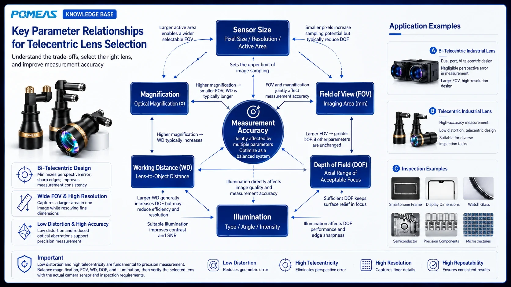
For a fixed-magnification telecentric lens, the relationship between optical magnification and object-side field of view can be estimated using the following formulas:
| Calculation | Estimation Formula | Description |
|---|---|---|
| Horizontal FOV | Effective Sensor Width ÷ Lens Magnification | Estimates the horizontal object-side field of view |
| Vertical FOV | Effective Sensor Height ÷ Lens Magnification | Estimates the vertical object-side field of view |
| Required Horizontal Magnification | Effective Sensor Width ÷ Required Horizontal FOV | Estimates magnification from the target horizontal FOV |
| Required Vertical Magnification | Effective Sensor Height ÷ Required Vertical FOV | Estimates magnification from the target vertical FOV |
In simple terms:
- Lower magnification generally provides a larger field of view.
- Higher magnification generally provides a smaller field of view.
- A larger camera sensor generally provides a larger FOV at the same lens magnification.
For example, consider a camera with an effective sensor area of 13.2 × 8.8 mm:
| Telecentric Magnification | Theoretical FOV | Imaging Characteristic |
|---|---|---|
| 0.5X | Approx. 26.4 × 17.6 mm | Larger coverage with fewer pixels allocated to a given object-space area |
| 1X | Approx. 13.2 × 8.8 mm | Object-side FOV is approximately equal to the effective sensor dimensions |
| 2X | Approx. 6.6 × 4.4 mm | Smaller FOV with more pixels concentrated on fine features |
These calculations are useful for preliminary lens selection. The actual FOV may vary slightly due to the real optical magnification, manufacturing tolerances, focusing conditions, and effective camera imaging area. Final values should be confirmed using the lens datasheet and actual imaging tests.
For additional camera and lens matching options, see the POMEAS industrial lens portfolio.
5. The Required FOV Should Not Be Exactly the Same as the Workpiece Size
A customer may say, “My part is 20 × 15 mm, so I need a 20 × 15 mm field of view.”
Although this works mathematically, a practical machine vision system normally requires additional FOV margin.
Factors to consider include:
- Part placement variation
- Fixture positioning tolerance
- Mechanical motion error
- Part-to-part dimensional variation
- Background area required for reliable edge detection
- Additional space for calibration and ROI adjustment
For example, if the workpiece measures 20 × 15 mm, the actual FOV may need to be 22 × 17 mm or larger. The required margin depends on fixture accuracy and product positioning stability.
However, the FOV should not be made unnecessarily large. As the field of view increases, the object-space size represented by each pixel also increases, reducing the system's ability to resolve small details.
A practical selection process therefore starts with the product dimensions and then accounts for expected positioning variation before calculating the required magnification.
6. Step 3: Working Distance Is Usually a Defined Optical Design Parameter
Working Distance (WD) is the specified object-side distance between the lens and the measurement plane, according to the lens manufacturer's definition.
Telecentric lenses behave differently from many conventional fixed focal length FA lenses. A conventional lens often allows focus adjustment across a certain object-distance range. A telecentric lens, however, is normally optimized around a specified working distance.
If the actual working distance deviates significantly from the designed WD, possible consequences include:
- Reduced image sharpness
- Degraded telecentricity
- Magnification variation
- Lower edge image quality
- Increased distortion or measurement error
- Actual FOV deviating from the specified value
Some telecentric lenses allow limited focusing adjustment, but this does not mean that the working distance can be changed arbitrarily. After focus adjustment, the actual magnification, image quality, and telecentric performance should still be verified.
Therefore, a requirement such as “the working distance can be anywhere from 110 to 200 mm” should not automatically be interpreted as meaning that one fixed-magnification telecentric lens can operate freely throughout that entire range.
A more reliable approach is to determine the actual working distance required by the mechanical system first, and then select a telecentric lens designed for that WD.
7. Step 4: Evaluate Depth of Field Together with Workpiece Height Variation
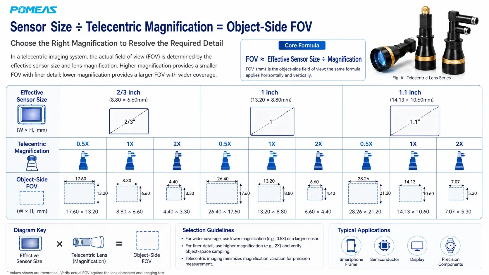
A telecentric lens can reduce magnification changes caused by object-height variation, but it does not provide unlimited depth of field.
Telecentricity and depth of field must be considered separately:
- Telecentricity: Primarily affects magnification stability and perspective error when the workpiece moves along the optical axis.
- Depth of Field (DOF): Determines the axial range over which the image remains sufficiently sharp for reliable inspection or measurement.
In other words, even if the apparent object size remains relatively stable, an edge can still become blurred once it moves outside the usable DOF. Measurement repeatability can then deteriorate.
For example, if a workpiece has a 5 mm height difference but the usable lens depth of field is only 2 mm, using a telecentric lens does not guarantee that all surfaces will remain simultaneously in focus.
Telecentric lens DOF is influenced by several factors, including:
- Lens magnification
- Aperture or effective F-number
- Camera pixel size
- Permissible circle of confusion
- Edge contrast required by the inspection algorithm
- Actual measurement accuracy requirement
In general, higher magnification places stricter requirements on focusing and usable depth of field. Stopping down the aperture may increase DOF, but an excessively small aperture can introduce diffraction and reduce image resolution. A balance is therefore required.
8. How Are Magnification, FOV, WD, DOF and Measurement Accuracy Related?
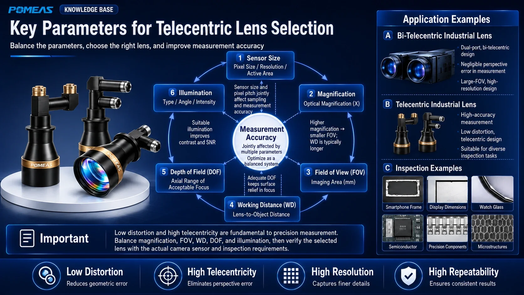
Telecentric lens selection is a system-level optimization problem. The goal is not to maximize one individual specification, but to balance multiple optical and mechanical requirements.
| Parameter | Main Influence | Selection Consideration |
|---|---|---|
| Camera Sensor Size | Determines usable imaging area and influences final FOV | The lens must fully cover the effective camera sensor |
| Magnification | Influences FOV and object-space sampling | Higher magnification generally produces a smaller FOV |
| Field of View (FOV) | Determines the area that can be inspected in one image | Allow margin for positioning and image processing |
| Working Distance (WD) | Affects machine structure and lens installation position | Keep the actual WD close to the lens design value |
| Depth of Field (DOF) | Defines the axial range that remains acceptably sharp | Should cover the relevant workpiece height variation |
| Lens Resolution | Affects fine-feature and edge imaging | Should match camera pixel size and inspection requirements |
| Distortion | Affects geometric scaling across the image | Precision measurement may still require calibration and compensation |
| Telecentricity | Affects magnification stability with object-height variation | More demanding accuracy and repeatability requirements require greater attention to telecentricity |
| Illumination | Affects edge contrast and measurement stability | Select according to silhouette measurement or surface inspection requirements |
A higher required measurement accuracy does not automatically mean that the highest possible lens magnification should be selected.
Increasing magnification can allocate more pixels to a smaller object area, but it also reduces the FOV, may reduce usable depth of field, and can increase lens size and mechanical integration difficulty.
The correct approach is to use sufficient magnification to meet the inspection requirement without unnecessarily over-magnifying the system.
9. Object-Space Pixel Size Is Not the Same as Final Measurement Accuracy
When selecting a telecentric lens, engineers often calculate how much object-space distance is represented by one camera pixel.
The common calculation is:
| Direction | Formula |
|---|---|
| Horizontal Object-Space Pixel Size | Horizontal FOV ÷ Horizontal Pixel Count |
| Vertical Object-Space Pixel Size | Vertical FOV ÷ Vertical Pixel Count |
For example, if the horizontal FOV is 20 mm and the camera has 4000 horizontal pixels, the theoretical object-space sampling is approximately 0.005 mm/pixel, or 5 µm/pixel.
However, this does not mean that the complete measurement system automatically provides 5 µm measurement accuracy.
Actual measurement performance is also influenced by:
- Lens resolving power and edge contrast
- Lens distortion and telecentricity
- Camera noise and pixel performance
- Illumination intensity and stability
- Calibration method and calibration target accuracy
- Mechanical vibration and structural rigidity
- Workpiece positioning and height variation
- Environmental temperature variation
- Edge detection algorithms and measurement repeatability
For this reason, µm/pixel should be treated as object-space sampling resolution, not as the guaranteed measurement accuracy of the system.
10. Distortion, Telecentricity, Resolution and Measurement Accuracy Are Different Specifications
These specifications are often discussed together, but each describes a different aspect of system performance.
Distortion
Distortion describes how geometric scale changes across the image. Lower distortion generally means that the captured geometry more closely represents the real object. However, precision measurement systems should still be calibrated.
Telecentricity
Telecentricity describes how closely the chief rays remain parallel in the telecentric space. Better object-side telecentricity generally results in smaller magnification changes when the workpiece moves along the optical axis.
Resolution
Optical resolution describes the lens's ability to reproduce fine detail and edge information. A lens with very low distortion does not necessarily provide sufficient resolving power for a high-resolution camera.
Measurement Accuracy
Measurement accuracy is a system-level result. It depends on the lens, camera, illumination, calibration method, mechanical structure, environmental conditions, and software algorithms.
Therefore, a specification such as “distortion below 0.02%” does not by itself guarantee a specific micron-level system accuracy. Similarly, a 25-megapixel camera does not automatically produce more stable measurements than a properly matched 5-megapixel system.
11. Object-Space Telecentric, Bi-Telecentric or Telecentric Zoom Lens: Which Should You Choose?
Object-Space Telecentric Lens
An object-space telecentric lens is designed primarily to minimize magnification variation caused by object-side height or position changes. It is suitable for many machine vision dimensional measurement applications.
Bi-Telecentric Lens
A bi-telecentric lens uses telecentric optical design on both the object side and image side. This provides greater control over object-space magnification variation and image-side chief ray angles, making it suitable for applications with demanding requirements for measurement consistency and imaging stability.
Telecentric Zoom Lens
A telecentric zoom lens is useful when the application needs adjustable FOV or must accommodate multiple product sizes while maintaining telecentric imaging characteristics.
However, the usable FOV, depth of field, working distance, distortion, magnification repeatability, and calibration strategy should be evaluated at the required zoom positions.
| Lens Type | Best Suited For |
|---|---|
| Fixed-Magnification Object-Space Telecentric Lens | Dimensional measurement with a fixed product size and fixed FOV |
| Bi-Telecentric Lens | High-consistency, high-precision and large-sensor measurement applications |
| Telecentric Zoom Lens | Multiple product sizes, adjustable FOV and R&D or flexible inspection systems |
12. What Illumination Should Be Used with a Telecentric Lens?
The lens forms the image, but reliable edge extraction also depends heavily on illumination.
Silhouette and Dimensional Measurement
For external profiles, hole diameters, spacing, and slot-width measurement, backlighting is often the first illumination method to evaluate.
For higher-accuracy applications, thicker components, or objects whose edges are prone to halo or blur, a collimated backlight or telecentric parallel backlight may provide more stable contour contrast.
Surface Feature Inspection
For scratches, printed characters, solder pads, textures, and other surface features, the illumination method should be selected according to the material and surface geometry. Common options include coaxial illumination, ring lighting, bar lighting, dome lighting, and polarized illumination.
Reflective Metal and Glass
For highly reflective surfaces, simply increasing brightness is rarely the best solution. It is more important to control the incident angle and reflection direction to reduce local overexposure and stray light.
For precision profile measurement, a sharp, stable, and repeatable edge is more important than producing an image that merely appears bright.
See POMEAS machine vision lighting and optical accessories for additional illumination options.
13. Common Telecentric Lens Selection Mistakes
Mistake 1: Selecting Magnification Without Considering Sensor Size
The same magnification produces different fields of view with different sensor sizes. Without the effective sensor dimensions, the FOV cannot be determined accurately.
Mistake 2: Setting the FOV Equal to the Exact Workpiece Size
Without margin for product displacement and image-processing requirements, the workpiece can easily move outside the usable image area during actual operation.
Mistake 3: Assuming the Working Distance Can Be Changed Freely
Telecentric lenses are generally designed around a specified WD. Significant deviation can affect sharpness, magnification, distortion, and telecentric performance.
Mistake 4: Assuming a Telecentric Lens Has Unlimited Depth of Field
Telecentric imaging improves magnification stability, but the image still becomes blurred when the object moves outside the usable depth of field.
Mistake 5: Treating Theoretical Pixel Size as Final Measurement Accuracy
Object-space pixel size only describes sampling. Final measurement accuracy also depends on the optics, illumination, calibration, mechanics, environment, and algorithms.
Mistake 6: Checking Only Center Sharpness
Precision measurement often uses a large portion of the image. Image quality should therefore be evaluated at the center, edges, and corners of the usable FOV.
Mistake 7: Supporting Only the Camera When Using a Large Telecentric Lens
Large-FOV telecentric lenses can be relatively heavy. If the lens body is left unsupported, vibration or mechanical deflection may affect focus, calibration, and measurement repeatability. A rigid lens support should be considered where necessary.
14. POMEAS Telecentric Lens Selection Process
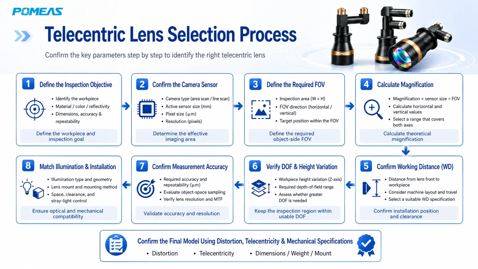
In practical projects, selecting the nearest magnification from a catalog is rarely sufficient. A more reliable telecentric lens selection guide follows the steps below.
Step 1: Define the Inspection Target
Determine whether the system will measure hole diameters, spacing, edges, profiles, or surface features. Confirm the required accuracy and repeatability.
Step 2: Confirm Camera Specifications
Confirm the camera model, effective sensor dimensions, resolution, pixel size, and lens mount.
Step 3: Determine the Actual Required FOV
Calculate the required field of view based on the workpiece size, expected positioning variation, and additional image-processing margin.
Step 4: Calculate the Required Magnification
Calculate magnification independently from the sensor width and height, and confirm that both horizontal and vertical directions cover the required object area.
Step 5: Confirm Working Distance and Installation Space
Confirm the available distance between the lens and workpiece. Also check lens length, diameter, weight, camera clearance, and space required for illumination.
Step 6: Confirm Depth of Field and Workpiece Height Variation
Verify that all critical measurement features remain within the usable depth of field.
Step 7: Evaluate Measurement Performance
Consider object-space pixel size, lens resolution, distortion, telecentricity, calibration conditions, and mechanical stability to determine whether the complete system can meet the measurement requirement.
Step 8: Match the Illumination and Mechanical Structure
Select backlighting, collimated illumination, coaxial illumination, or another suitable lighting method, and ensure that the camera and lens are mounted rigidly enough for repeatable measurement.
Evaluating these parameters together reduces the risk of choosing a lens that appears suitable on paper but cannot meet the actual installation or measurement requirements.
15. What Information Should You Provide for Telecentric Lens Selection?
To help POMEAS recommend a suitable telecentric lens more efficiently, provide as much of the following information as possible:
- Industrial camera model
- Effective sensor dimensions
- Camera resolution
- Pixel size
- Camera mount type
- Workpiece dimensions
- Required field of view
- Working distance
- Workpiece height variation
- Features or dimensions to be measured
- Required accuracy and repeatability
- Smallest feature that must be detected or measured
- Workpiece material and surface condition
- Preferred or existing illumination method
- Installation space limitations
- Sample images or mechanical drawings
If all parameters are not yet available, start with the camera sensor size, required FOV, working distance, and measurement accuracy requirement. These four parameters are usually sufficient for an initial evaluation of magnification and lens series.
16. Related Products and Resources
If you are still evaluating the appropriate lens type, optical configuration, or illumination method, the following POMEAS resources may help:
- POMEAS Industrial and Machine Vision Lens Solutions
- What Is a Telecentric Lens? Working Principle, Types and When to Use One
- POMEAS Machine Vision and Precision Measurement Products
- Machine Vision Lighting and Optical Accessories
- Contact POMEAS for Telecentric Lens Selection Support
Selecting a telecentric lens does not end with choosing a magnification. A stable precision measurement system requires the camera, lens, illumination, mechanical structure, calibration method, and software to be evaluated as a complete optical measurement system.
17. FAQ: Frequently Asked Questions About Telecentric Lens Selection
Q1: Does higher telecentric lens magnification always provide higher measurement accuracy?
No. Higher magnification generally allocates more pixels to a smaller object area, but it also reduces the field of view and may impose stricter requirements on depth of field, focusing, and mechanical installation. Final measurement accuracy also depends on lens resolution, illumination, calibration, and mechanical stability.
Q2: How do I calculate the FOV of a telecentric lens?
As a preliminary estimate, divide the effective camera sensor width and height by the telecentric lens magnification. Calculate the horizontal and vertical directions separately. Final FOV should be confirmed using the lens specifications and actual imaging results.
Q3: Can the working distance of a telecentric lens be changed?
Some models allow limited focusing adjustment, but telecentric lenses are generally optimized around a specified working distance. Significant deviation from the designed WD can affect image sharpness, magnification, distortion, and telecentricity.
Q4: Does a telecentric lens completely eliminate perspective error?
A telecentric lens can significantly reduce perspective error and magnification variation caused by object-height changes. However, real lenses still have finite telecentricity error, distortion, and manufacturing tolerances. The final performance should be evaluated together with calibration results.
Q5: Do telecentric lenses always have a large depth of field?
No. A telecentric lens does not provide unlimited depth of field. DOF is still affected by magnification, aperture, camera pixel size, acceptable blur, and the imaging requirements of the measurement algorithm.
Q6: How should I choose between a 0.5X, 1X and 2X telecentric lens?
The required magnification should be calculated from the effective camera sensor dimensions and target field of view. A 0.5X lens generally provides a larger FOV, a 1X lens provides an object-side FOV close to the effective sensor dimensions, and a 2X lens provides a smaller FOV for observing finer features.
Q7: Does a telecentric lens always require a collimated backlight?
No. Standard backlighting is often suitable for silhouette and dimensional measurement. For higher-precision contour measurement, thicker components, or applications sensitive to edge blur, collimated backlighting can be evaluated. Surface inspection may instead require coaxial, ring, bar, dome, or other front-lighting methods.
Q8: Is a bi-telecentric lens always better than an object-space telecentric lens?
Not necessarily. Bi-telecentric lenses can provide greater object-side and image-side stability, but they may also involve larger optics, higher cost, and more demanding installation requirements. The choice should depend on sensor size, accuracy requirements, optical geometry, and system constraints.
Q9: If the theoretical object-space pixel size is 5 µm, can the system achieve 5 µm measurement accuracy?
Not automatically. A value of 5 µm/pixel describes the theoretical spatial sampling of the imaging system. Final measurement accuracy also depends on the lens, illumination, calibration, mechanics, environment, camera performance, and measurement algorithm, and should be verified through actual testing.
Further reading: the test methods behind this article are documented in POMEAS Technical Reference how the distortion and telecentricity of a lens are measured (§§8.7 畸变).

Subscribe to Our Newsletter
Simply enter your email to receive the latest news and insights from Pomeas. Stay connected with Pomeas and be the first to discover new innovations in optical excellence.


