Knowledge
Motorized Zoom Lens PLC Integration: What the Handshake Must Cover
A PLC does not control a motorized zoom lens; it triggers a controlled sequence and refuses to fire a camera until the optics confirm they are where the recipe says they should be. That distinction decides whether an integration works on the first shift or haunts production for months. The zoom lens side is a motion system with its own controller and a documented serial interface; the PLC side is a state machine that must select the magnification, wait for an in-position confirmation, and only then expose the frame. This article describes the handshake at a level that holds for any brand, separates what is published from what is model-specific, and lists the interlocks that prevent frames taken at the wrong magnification.
What the PLC actually does — and does not do
Three jobs belong to the PLC in a zoom-lens cell: recipe selection, sequencing and interlocking. Recipe selection means choosing the magnification for the current product or inspection step. Sequencing means ordering the moves: position the optics, then trigger the exposure, then hand the frame to the vision system. Interlocking means refusing to continue when a step fails — a move that does not confirm, a timeout, a missing frame. Motion itself stays with the lens controller: the POMEAS motorized families are commanded over RS-232 with a documented serial protocol, and position feedback reports the magnification state back to the integrator. A PLC that tries to own the motion loop by bit-banging commands faster than the controller accepts them produces the classic symptom of a station that works when stepped manually and fails at line speed.
The three integration levels
Integrations fall into three levels of sophistication, and it is worth knowing which one a project actually needs before writing any code. Level one is operator-driven: a person selects magnification, the PLC only triggers the camera. Level two is recipe-driven: the PLC sends a magnification command per product changeover and waits for confirmation — this is where most AOI and multi-station cells land. Level three is closed loop: the controller reports magnification position after every move, and the cell verifies it before every exposure, so a drifted position is caught between frames rather than after a batch. The third level is the only one that protects against silent drift, and it is the reason the serial protocol matters more than the motor: a documented protocol with readable position turns the lens into a sensor as well as an actuator.
The generic handshake, step by step
Whatever the brand, the sequence is the same five steps. First, the PLC selects the recipe or target magnification for the current inspection step. Second, it issues the move command. Third, it waits for confirmation — an in-position signal, a busy flag clearing, or a reported position matching the setpoint within tolerance. Fourth, it triggers the camera exposure. Fifth, it receives frame-done or the inspection result and continues. Every one of those steps has a failure mode, and the interlock list decides whether a failure produces a rejected frame or a rejected batch.
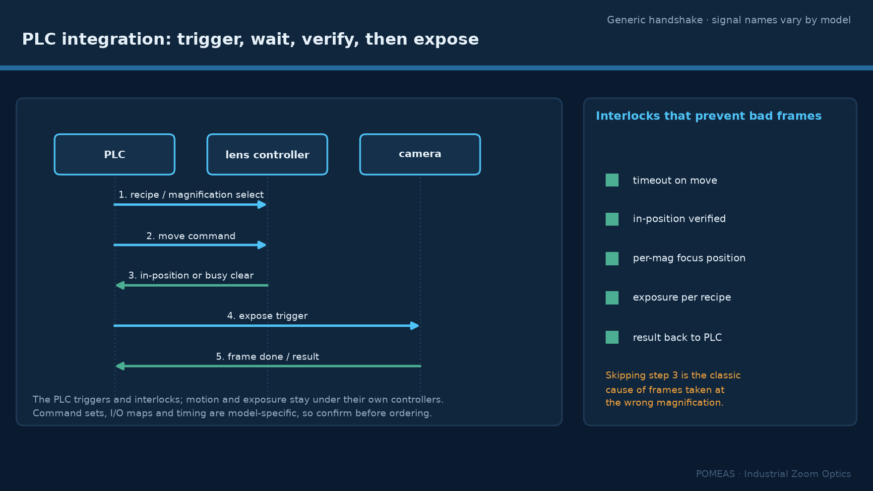
Step three is the one integrators skip, and skipping it is the classic cause of frames captured at the wrong magnification. The failure is invisible in the image itself at a glance — the frame is sharp, just at 2× instead of 4× — and it surfaces later as measurement drift or as a vision tool that stops matching. If the controller reports position over the serial link, the PLC or vision system can compare the reported value against the setpoint each cycle; if it only offers a busy output, the cell can still interlock on that signal, but it cannot detect drift, and periodic verification with a calibration target becomes the compensating control.
What must be confirmed per model before ordering
Several facts are model-specific and must come from the product documentation or the factory; they should be on the integration checklist before a purchase order is signed. The command set: which commands the serial protocol exposes for magnification and focus, and how position is read back. The electrical interface: whether the lens controller offers discrete I/O in addition to RS-232, and the meaning of each line. Timing: the travel time between magnification endpoints, which sets the cycle-time budget when a cell changes magnification per part. Repeatability: how consistently the lens returns to a commanded magnification, which the repeatable-magnification test method measures over repeated cycles. Published values for the POMEAS motorized families, including the 12.5× motorized model and the 6.5× motorized model, cover the optical table and the control interface; anything beyond that is integration-specific and should be verified with engineering rather than assumed.
Failure modes and the interlocks that catch them
Five failure modes account for most field problems. A move that never completes — caught by a timeout on the in-position wait. A position that completes but drifts — caught by comparing reported position with the setpoint, or by periodic calibration-target checks. A focus that no longer holds after a magnification change — this is not a fault but a property of optics, because depth of field shrinks from millimetres to tens of microns across a zoom range, and the cell needs a per-magnification focus position or a motorized focus axis. An exposure fired during motion — caught by sequencing the trigger strictly after confirmation. A frame that never arrives — caught by a frame-done timeout with a defined retry policy. None of these requires exotic hardware; all five are one-line interlocks in the PLC program, and the cost of adding them is minutes compared with the cost of tracing a drifted measurement back to its cause.
Where the vision software should own the lens instead
Not every cell needs the PLC in the optics path at all. When the vision software already sequences lighting, exposure and part presence, giving it direct serial control of the lens removes a layer and keeps optical state in the same program that interprets the image; the PLC then only triggers the inspection, as it would for any camera. The division that works in practice: the PLC owns machine-level interlocks — part present, safety, fixture state — while the vision system owns everything that is expressed in optical units. Problems appear at the seam when both sides try to command the lens, or when neither does; decide the ownership before integration starts, and record it in the cell documentation.
Frequently asked questions
Can a PLC control a motorized zoom lens directly?
Usually not directly over the serial link: PLCs speak fieldbus and discrete I/O, while the lens controller speaks RS-232. The standard architectures are a lens controller that translates, a small gateway node, or the vision PC acting as the serial master with the PLC triggering the sequence. The POMEAS serial protocol is documented so that any of these masters can implement it.
Which signal does the PLC actually send to change magnification?
At minimum, a target magnification value — a preset number, an index into a stored position list, or an absolute command over the serial link. Signal names and command formats are controller-specific, so the exact set must be confirmed for the model in the purchase order; the generic handshake around them does not change.
How does the PLC know the magnification has been reached?
Either the controller reports position over the serial link, or it provides a discrete in-position or busy-clear output. Position read-back is stronger because it verifies the value, not just the motion; with a busy output alone the cell can interlock but cannot detect drift between calibration checks.
Does the focus need to change when magnification changes?
In general yes: depth of field falls from millimetres at the bottom of a zoom range to tens of microns at the top, so a station that changes magnification per step needs a stored focus position per magnification or a motorized focus axis. Treating focus as a per-recipe value is the single most common missing item in first integrations.
Should the vision software control the lens instead of the PLC?
Often, yes. If the vision system already sequences lighting and exposure, direct serial control keeps the optical state with the program that interprets the frames, and the PLC keeps machine-level interlocks. The failure pattern to avoid is both masters commanding the lens concurrently; assign ownership once and document it.
What must be confirmed with the manufacturer before ordering?
The command set and position read-back format, the electrical interface options, travel time across the magnification range for the cycle-time budget, and magnification repeatability over repeated cycles. The optical tables for the motorized families are published; timing and integration details should be verified with engineering for the specific model.

Subscribe to Our Newsletter
Simply enter your email to receive the latest news and insights from Pomeas. Stay connected with Pomeas and be the first to discover new innovations in optical excellence.


