How Can Medical Bone Screws Be Measured Quickly and Consistently?
Medical bone screws with a diameter of approximately 3 mm may contain threads, steps, tapered surfaces and specially shaped heads. A telecentric in-line image measuring system can capture their profiles and perform non-contact inspection of length, diameter, thread pitch, angles and other critical dimensions.
Inspection Target: A Small Medical Bone Screw with Complex Features
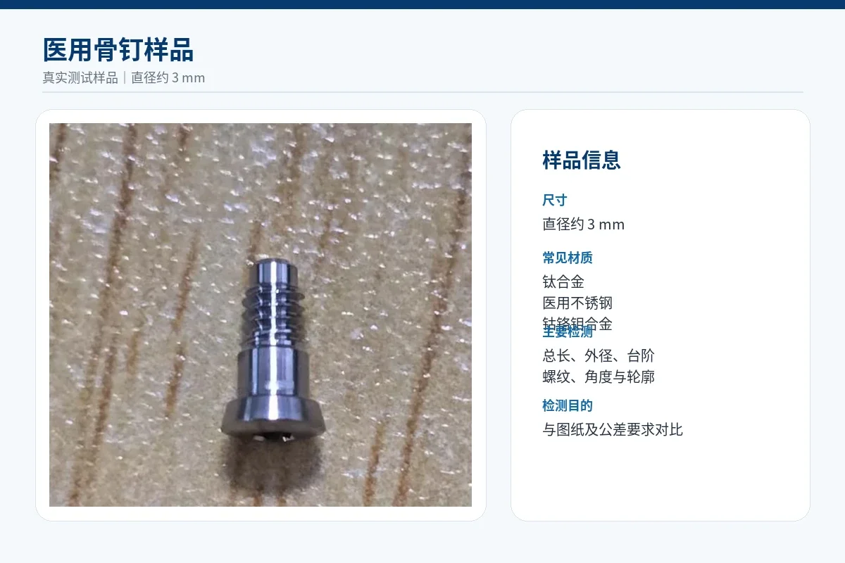
The inspected sample is a small medical bone screw with an approximate diameter of 3 mm. Common bone screw materials include titanium alloys, medical-grade stainless steel and cobalt-chromium-molybdenum alloys.
The purpose of the inspection is to compare the actual machined dimensions with the engineering drawing and tolerance requirements, allowing dimensional deviations to be identified during quality control.
Depending on the design of the screw and the drawing requirements, common inspection items include:
- Overall length, threaded length and section distances;
- Shaft diameter, major thread diameter and minor thread diameter;
- Thread pitch, thread profile and spacing between adjacent features;
- Head diameter, head height and step dimensions;
- Taper angles, radii and irregular profile dimensions;
- Part position, runout and external profile defects.
Why Are Medical Bone Screws Difficult to Measure?
Small Features
Bone screws and their threads, steps and radii may only measure a few millimetres. A small manual probing error can affect the final result.
Multiple Geometries
One part may contain straight lines, circles, arcs, angles, threads and irregular profiles, making complete inspection difficult with a single conventional gauge.
Reflective Metal Surfaces
Titanium and stainless-steel surfaces can produce reflections. Unsuitable lighting may cause overexposure, blurred edges or unstable profile extraction.
Operator Variation
Measuring force, probing position and operating habits may vary between inspectors and production batches.
Batch Inspection Speed
Production inspection requires fewer repeated manual operations, less handwritten recording and faster measurement cycles.
Data Traceability
Measurement results may need to support quality records, dimensional trend analysis and investigation of non-conforming batches.
How Does an In-Line Image Measuring System Inspect a Bone Screw?
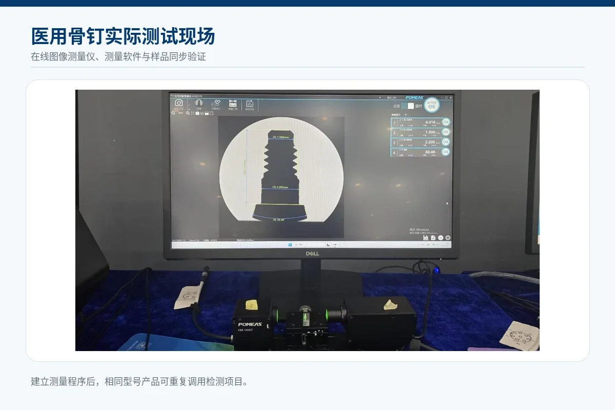
The POMEAS HM Telecentric Measurement System combines a light transmitter, receiver, telecentric optical structure, CMOS imaging unit, vision controller and dimensional measurement software.
The transmitter produces collimated green LED light. The bone screw is positioned between the transmitter and receiver, where it blocks the light and creates a high-contrast silhouette.
The receiver captures this projected profile through the CMOS imaging unit. The software then extracts the edges, constructs measurement features and calculates the required dimensions.
Both the transmitting and receiving sides use telecentric optical structures. When the workpiece moves slightly forward or backward within the permitted depth range, the change in image magnification is reduced, helping maintain stable profile measurement.
Additional machine vision lenses, cameras, illumination products and dimensional inspection systems can be found in the POMEAS product centre .
Why Use Telecentric Profile Imaging?
In a conventional imaging system, the apparent size of a part may change when its position changes along the optical axis.
A telecentric optical system primarily accepts near-parallel rays, reducing magnification changes caused by small positional variations.
For a bone screw containing fine threads, steps and small contour features, stable edge imaging is an important basis for repeatable measurement and tolerance judgement.
Medical Bone Screw Inspection Workflow
What Can Be Displayed in the Measurement Results?
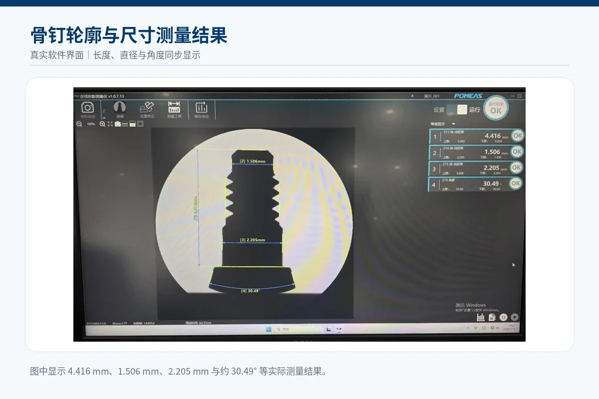
Multiple tools can be created for different bone screw features within the measurement software. Dimensions visible from the same direction and within the same field can be calculated from a single image capture.
- Distance between two detected lines;
- Shaft diameter and threaded-section diameter;
- Head width and step height;
- Thread pitch and section length;
- Angles, radii and profile deviations;
- Burrs, foreign material and profile defect distance.
After the program has been created for one bone screw model, it can be reused for parts of the same type, reducing repeated manual probing and data entry.
HM-1120 Key Specifications
The HM-1120 is the large-field model in the HM series. Its full measuring range is φ120 mm, making it more suitable for long parts, multiple parts in one field or complete profile measurement over a larger inspection area.
| Model | HM-1120 |
|---|---|
| Product type | Large-field telecentric in-line image measuring system |
| Transmitter-to-receiver distance | 436.7 mm |
| Full measuring range | φ120 mm |
| High-accuracy measuring area | φ60 mm |
| Depth range in full measuring area | 40 mm |
| Depth range in high-accuracy area | 20 mm |
| Exposure time | 35 / 70 / 150 µs, three selectable levels |
| Capture time / trigger interval | FULL mode: approximately 34 ms (approximately 30 fps); 1/4 width and height mode: approximately 5 ms (approximately 200 fps) |
| Light source | InGaN green LED |
| Measurement position accuracy in the high-accuracy area | ±2.5 µm |
| Measurement position accuracy in the full area | ±3.5 µm |
| Repeatability | ±0.2 µm |
| Enclosure protection | IP64 |
| Operating temperature | 0 to 45°C |
| Operating humidity | Up to 85% RH, non-condensing |
| Main materials | Aluminium / PBT |
| Weight | Transmitter: approximately 5,900 g; Receiver: approximately 7,900 g; Base: approximately 4,300 g |
Note: The accuracy values above are based on the standard test conditions stated in the HM series product documentation. Actual inspection performance may be influenced by profile contrast, workpiece positioning, vibration, calibration, measurement algorithms and environmental conditions. Sample testing is recommended before final model selection.
Does a 3 mm Bone Screw Always Require the HM-1120?
The original application report shows a high-accuracy, small-field HM configuration. The HM-1120 product image is used on this page to present the large-field capabilities available within the HM series.
The final model should therefore be selected from the drawing, tolerance requirements and sample test results rather than from the product name alone. Other optical inspection and dimensional measurement solutions can be viewed in the POMEAS product centre .
What Improvements Can the System Provide?
Reduced Operator Error
Fixed measurement programs and edge detection rules help reduce variation caused by manual probing.
Multiple Dimensions in One Image
Length, diameter, distance, angle, radius and profile tools can be applied within the same image.
Improved Batch Consistency
The same program can be reused for identical parts, standardising measurement positions and judgement rules.
Non-Contact Inspection
The part does not need to be continuously clamped by a contact gauge, which is useful for small and precision components.
Dimensions and Profile Defects
In addition to dimensional measurement, profile differences may be used to detect burrs, foreign objects and certain external defects.
Measurement Data Recording
Results can support quality records, process trend analysis and investigation of abnormal batches.
What Information Is Required Before System Selection?
To determine the measuring range, required accuracy, optical configuration and automation method, provide as much of the following information as possible:
- A product photo or 2D engineering drawing;
- Maximum part size and overall length;
- Exact dimensions and locations to be inspected;
- Tolerance requirement for each dimension;
- Smallest thread, radius or step feature;
- Required parts per minute or parts per hour;
- Static inspection, conveyor inspection or automatic loading;
- Data storage, communication and production-line integration requirements.
More application information and machine vision articles are available in POMEAS machine vision insights and application updates .
Medical Bone Screw Inspection FAQ
Can the system measure bone screw thread pitch?
Yes, provided that the thread profile is clearly imaged and adjacent thread features can be detected consistently. Actual performance depends on thread pitch, measuring range, system resolution and sample test results.
Will reflections from the metal surface affect measurement?
External profile measurement mainly uses transmitted collimated light to create a silhouette, so it is less sensitive to direct reflection from the metal surface. Additional ring, coaxial or low-angle lighting may be required for top slots, scratches or surface defects.
Can several dimensions be measured at the same time?
Yes. Multiple tools can be created for dimensions visible from the same direction and located within the same measuring field. The dimensions can then be calculated from one image capture.
Is the HM-1120 suitable for every medical bone screw?
No single model is suitable for every project. The HM-1120 prioritises a large field and complete profile coverage. Fine local structures or tighter tolerances may require a smaller-field, higher-accuracy HM model or another high-magnification optical configuration.
Can POMEAS evaluate the application from a drawing or photo?
An initial evaluation can be made from product photos, drawings, dimensions and tolerance requirements. For complex profiles or demanding accuracy requirements, an actual sample test is recommended. Contact POMEAS to submit the drawing and inspection requirements.
How are small medical components such as bone screws checked against drawing tolerances?
The system extracts edges and constructs measurement features from the image, then compares the measured values with the drawing dimensions and tolerance requirements. Once a measurement program has been created for one model, it can be reused for parts of the same type, standardising measurement positions and judgement rules across production batches.
Evaluate Your Medical Bone Screw Inspection Application
Send a sample photo, engineering drawing or marked inspection location. POMEAS can initially evaluate the suitable measuring range, accuracy level, optical configuration and system model.



