Knowledge
Measuring Micro-Holes on Fiber Optic Components: a 10-Workpiece Inline Repeatability Test
Fiber optic assemblies often carry micro-holes of roughly 120 μm diameter that must be measured inline – not sampled offline in a lab. Huatai Automation, a Chinese automation integrator, ran a structured repeatability test on a POMEAS HM-series inline image measuring head to see what the system actually delivers on such a part. This article publishes the raw statistics in full, together with the conditions that bound their interpretation.
Test setup
- Equipment: POMEAS HM-series inline image measuring head (dual-telecentric shadow projection, green LED parallel light, CMOS receiver), POMEAS inline measuring software v1.1.0.5.
- Workpieces: 10 fiber optic component samples, individually numbered 1–1 … 2-5 on the tray.
- Features measured: hole 1 diameter, hole 2 diameter, hole-to-hole (center-to-center) distance. All values in μm.
- Procedure: each workpiece was clamped once and measured 5 consecutive times without re-loading. Test date 2026-11-02.
- Reference specification: the HM-1040 standard model of the series specifies a φ40 mm measuring range, ±0.08 μm repeatability and ±1.0 μm measuring position accuracy (HM-series product manual, p. 12). The installed head is an HM-series model; its exact model designation is pending customer confirmation.
Raw statistics: 10 workpieces × 5 readings
The table below lists each workpiece's mean over its 5 readings. Every single reading, maximum, minimum, range and standard deviation per workpiece is preserved in the raw data file referenced at the end of this article; no unfavorable data has been removed.
| Workpiece | Hole 1 mean (μm) | Hole 2 mean (μm) | Hole-to-hole distance mean (μm) |
|---|---|---|---|
| 1 | 120.59 | 120.14 | 157.08 |
| 2 | 120.03 | 119.65 | 138.14 |
| 3 | 120.61 | 120.35 | 150.53 |
| 4 | 116.01 | 117.35 | 159.10 |
| 5 | 118.02 | 117.31 | 151.42 |
| 6 | 121.10 | 121.92 | 139.60 |
| 7 | 120.59 | 120.51 | 195.80 |
| 8 | 117.81 | 117.86 | 137.10 |
| 9 | 117.18 | 118.97 | 168.32 |
| 10 | 128.83 | 122.62 | 143.19 |
Across the 10 samples, hole 1 means range from 116.01 μm to 128.83 μm and hole-to-hole distances from 137.10 μm to 195.80 μm. This spread between different workpieces reflects genuine part-to-part dimensional differences of the samples – it is not measurement error.
Repeatability results (pooled, n = 50 per feature)
| Feature | Pooled within-piece σ (μm) | Largest single-piece range (μm) | Median single-piece range (μm) |
|---|---|---|---|
| Hole 1 diameter | 0.390 | 1.70 | 0.88 |
| Hole 2 diameter | 0.493 | 1.76 | 1.10 |
| Hole-to-hole distance | 0.496 | 2.10 | 1.09 |
The pooled standard deviation is computed across all 10 workpieces (50 readings per feature), which is a more conservative statement of repeatability than quoting the single best workpiece.
What this data does and does not prove
- Proven: under fixed clamping, the system's short-term repeatability on this part is at the 0.4–0.5 μm (1σ) level for all three features.
- Not proven: repeatability after re-clamping or re-loading each part. Fixed-position repeat tests exclude part handling effects; total inline capability requires a re-loading test.
- Not proven: absolute measurement accuracy. Repeatability bounds random error only; accuracy additionally requires a calibrated reference artifact.
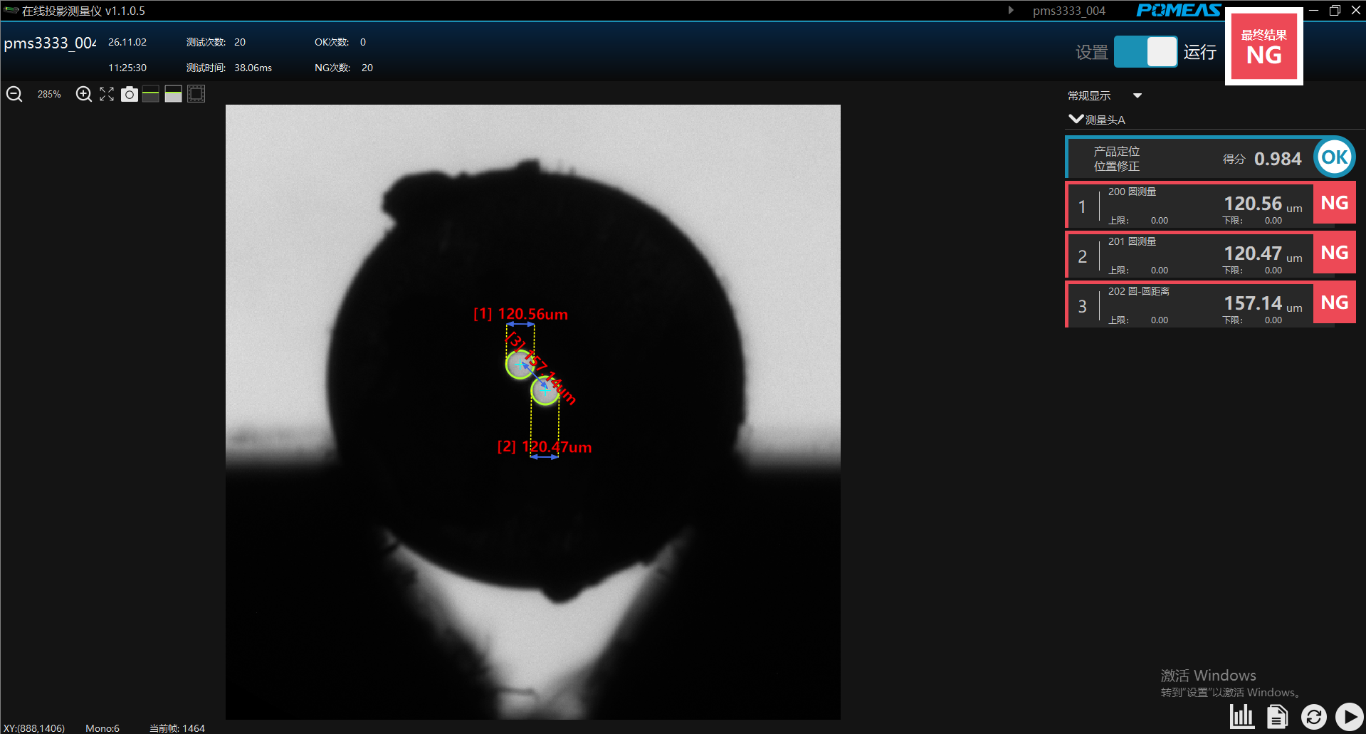
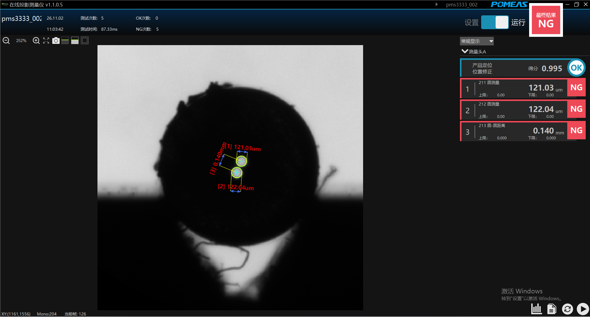
- Note: during the test the software tolerance limits had not yet been configured (upper/lower limits 0.000), so the software's NG flags in the screenshots are configuration artifacts, not part rejects.
Software evidence
The measuring software screenshots embedded in the source data show the POMEAS inline measuring software v1.1.0.5 with the "micro-probe A" toolset, product positioning correction scoring 0.984 (OK), and the three features reported live in μm. The shadow-projection image shows the two micro-holes inside the part silhouette.
Relevance for fiber optic production
The tested feature sizes – two ~120 μm holes with a ~140–196 μm center distance – are representative of fiber optic sub-components where both the hole diameter and the hole spacing determine coupling alignment. For related measurement tasks see our ferrule bore inspection method, our 0.025 mm fiber hole positioning case, and the HM-series selection guide.
- Ferrule bore inspection: diameter, concentricity, defects
- Submicron positioning of a 0.025 mm fiber hole
- Optical communications precision measurement solutions (hub)
FAQ
Why were all measurements flagged NG in the screenshots?
The tolerance upper/lower limits had not been configured during the test (both 0.000), so the software flagged every reading NG. This is a configuration state, not a part quality verdict.
Is the 0.39 μm standard deviation the same as accuracy?
No. It is a repeatability figure under fixed clamping. Absolute accuracy would require calibrated reference parts and a separate study.
Why are hole means different between the 10 workpieces?
Because the 10 samples genuinely differ in size. Between-workpiece spread is part variation, not measurement error.
Can the same test be repeated on other fiber optic parts?
Yes. The same protocol – 10 workpieces, 5 fixed-position readings, pooled σ per feature – is the baseline verification POMEAS runs with customers before line integration.

Subscribe to Our Newsletter
Simply enter your email to receive the latest news and insights from Pomeas. Stay connected with Pomeas and be the first to discover new innovations in optical excellence.


