Knowledge
Fiber Optic Ferrule Bore Inspection: Diameter, Concentricity and Defects Under Backlight
The ferrule is the precision core of any fiber connector: a rigid body carrying one or more holes that hold the glass fiber at a defined position. Whether it is a ceramic single-fiber ferrule holding a 125 µm cladding (typical industry value) or a plastic multi-core housing whose coupling holes are tens of micrometers across, the holes decide where the fiber ends up — and the practical way to check them on a production line is to image them. This article sets out what a ferrule bore inspection has to deliver, how to size the optics for holes of this scale, and why backlight rather than epi-illumination is the working choice for bore geometry — illustrated with a real backlight image of a multi-core plastic ferrule.
Other languages: 中文 · Español · Français · Русский · العربية
1. What the Inspection Has to Deliver
A ferrule bore check is not one measurement but a short list of judgments, each with its own optical requirement:
- Bore diameter and ovality. The hole must accept the fiber with the designed clearance. On the multi-core plastic ferrule in our project record the coupling hole is about 0.025 mm against a fiber of about 0.020 mm — a mechanical margin of roughly 2.5 µm per side.
- Bore edge condition. Burrs, chips and cracks at the rim are the defects that damage fiber or block insertion; they live on a contour a few pixels wide and need enough sampling to be distinguishable from the edge itself.
- Bore contamination or blockage. Debris, dust or plastic flash inside the opening. On a backlight image an unobstructed hole transmits as a clean bright disc, so a blocked or partly blocked hole changes the brightness profile of the disc — one of the few defects that is visible from the brightness alone.
- Bore position. The center coordinates of each hole, for insertion guidance and for the pitch check on multi-core parts.
- Concentricity. The distance between the bore center and the center of the ferrule outer diameter, which is what actually positions the fiber inside the connector.
2. How Many Pixels Does a Bore Need
The sampling rule for a judged edge is 3–5 pixels across the critical dimension. Centering to a stated accuracy needs more than the diameter rule suggests, because the center is derived from two contours: a useful working number is at least 3 pixels across the positioning tolerance itself.
Two worked cases show the range:
- Ceramic single-fiber ferrule. The bore is typically about 126 µm for a 125 µm cladding (typical industry value), but concentricity forces the field of view to cover the outer diameter as well — on the order of 3 mm. On a 2448-pixel sensor that is about 1.2 µm per pixel, so the 126 µm bore is sampled with roughly 100 pixels: diameter is easy, concentricity sets the field of view.
- Multi-core plastic housing (project record). Coupling hole 0.025 mm, fiber 0.020 mm, positioning accuracy ≤ 1 µm, working field of view 7 mm on a 9344 × 7000 sensor. That gives 7000 µm ÷ 9344 px ≈ 0.75 µm/px (own calculation, estimate): 33 pixels across the bore and about 3 pixels across the 2.5 µm side margin.
The required object-side magnification follows from the sensor: pixel size ÷ target µm-per-px. For the second case, 3.2 µm ÷ 0.75 ≈ 4.3X on the sensor. Where a continuous-zoom body is converted to an APO objective, remember the adapter factor: total magnification = zoom × APO objective × 0.55.
3. Why Backlight Is the Working Choice for Bore Geometry
A bore is a hole. Its defining geometry is the boundary between material and opening, and the cleanest way to see that boundary is to put the light behind the part: the opening transmits, the body does not, and the hole appears as a bright disc on a dark body. Every geometric judgment — diameter, center, pitch, ovality — is read off that single contour.
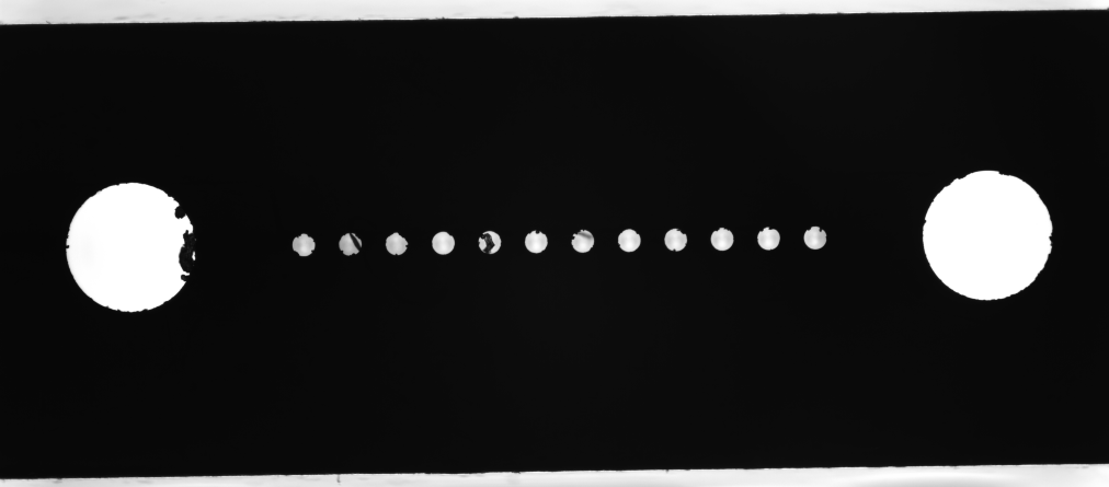
The illumination quality decides whether that contour is stable. On translucent plastic, diffuse ring or area light creates a penumbra around the opening: the apparent edge shifts with brightness and part position, and the calculated center drifts cycle to cycle. The parallel backlight used in the project record has a half-angle below 0.1° and better than 90 % uniformity over the useful area, which keeps the gray transition at the rim narrow and repeatable — this is what makes sub-micrometer centering possible at all.
4. Center, Pitch and Concentricity from the Same Image
- Center is the centroid of the bore contour. With sub-pixel edge extraction on a narrow gray transition, repeatability in the sub-micrometer range is what the project record achieved — the optical chain supplies the sharp edge; the algorithm does the rest.
- Pitch on multi-core parts is the distance between adjacent centers. Telecentric optics keep that measurement free of perspective distortion, which matters wherever the pitch value itself is a judged quantity.
- Concentricity needs the bore contour and the outer-diameter contour in the same field of view, with the part properly clamped; it is the ratio of that distance to the tolerance that decides pass or fail.
- Depth of field caution: you image the rim of the hole, not its bottom. For a through-hole, backlight shows the opening directly; for a blind hole, the hole depth sets the depth-of-field requirement and the illumination has to work at an angle.
5. What the Camera Sees at the Rim
- Rim burrs and chips — bright or dark intrusions on the contour; visible when the sampling is sufficient.
- Ovality — the disc is not round; a diameter measurement in two directions catches it.
- Debris or flash in the bore — the bright disc is dimmer, patchy or missing.
- Rim roughness — visible only at detail scale, which is why the overview alone is not enough for a rim-quality judgment.
What plain backlight does not show: subsurface defects inside the material around the opening, and anything happening below the rim inside a blind hole. Those need a different illumination geometry or a destructive check — worth stating in the inspection plan rather than discovering on the line.
6. Worked Example: A 0.025 mm Coupling Hole (Project Record)
| Parameter | Value | Source |
|---|---|---|
| Coupling hole diameter | 0.025 mm (25 µm) | Project record |
| Fiber diameter to be inserted | 0.020 mm (20 µm) | Project record |
| Positioning accuracy required | ≤ 1 µm | Project record |
| Working field of view | 7 mm | Project record |
| Sensor | 65 MP global-shutter CMOS, 3.2 µm pixel, 9344 × 7000 px | Product documentation |
| Illumination | Flat parallel backlight, half-angle < 0.1°, uniformity > 90 % | Product documentation |
| Resolution per pixel | ≈ 0.75 µm/px | Own calculation (estimate) |
The system imaged the hole with sharp edges and stable contrast, and guided the insertion mechanism within the ≤ 1 µm positioning requirement. The full solution write-up of this project is on our 0.025 mm fiber hole application page.
FAQ
What does a ferrule bore inspection measure?
The working checklist is bore diameter and ovality, bore edge condition (burrs, chips, cracks), bore contamination or blockage, the center position of each hole for insertion guidance and pitch, and the concentricity between the bore center and the ferrule outer-diameter center. The last one is what actually positions the fiber inside the connector.
Why is backlight used for ferrule bore inspection instead of coaxial light?
A bore is a hole, and its geometry is the boundary between material and opening. Backlight makes the opening transmit and the body stay dark, so the hole reads as a bright disc on a dark body with a single stable contour. Coaxial epi-illumination is the right tool for a fiber already seated in the end face, not for the bore geometry itself.
How many pixels are needed across the bore?
The sampling rule is 3–5 pixels across the critical dimension, but centering accuracy needs more: plan on at least 3 pixels across the positioning tolerance itself. In a documented case with a 0.025 mm hole, a 7 mm field of view on a 9344-pixel sensor gives about 0.75 µm per pixel — 33 pixels across the bore and about 3 pixels across the 2.5 µm side margin.
How is total magnification calculated for a zoom lens with an APO objective?
Total magnification = zoom magnification × APO objective magnification × 0.55, where 0.55 is the coupling factor of the APO adapter ring. Skipping the factor overstates magnification by nearly half and corrupts every field-of-view and pixel-size calculation built on it.
Why does the backlight have to be parallel?
On translucent plastic, diffuse light creates a penumbra around the opening: the apparent edge shifts with brightness and part position, and the calculated center drifts from cycle to cycle. A parallel backlight with a half-angle below 0.1° keeps the gray transition at the rim narrow and repeatable, which is what makes sub-micrometer centering possible.
Can the same image give hole diameter and concentricity?
Yes, provided the field of view covers the bore and the ferrule outer diameter at the same time and the optics are telecentric. Concentricity is the distance between the two contour centers; if the outer diameter is out of frame, only the bore diameter and center can be judged.
What defects are visible on the bore rim, and what are not?
Visible: rim burrs and chips, ovality, debris or plastic flash blocking the opening, and rim roughness at detail magnification. Not visible with plain backlight: subsurface defects in the material around the opening and anything below the rim inside a blind hole.
Does the hole depth matter for the imaging design?
Yes. The camera images the rim of the hole, not the bottom. A through-hole under backlight shows the opening directly; a blind hole makes the depth part of the depth-of-field budget and usually needs illumination at an angle rather than straight backlight.
Further Reading
- V-Groove and Fiber Array (FAU) End-Face Inspection
- Fiber Connector End-Face Inspection Case: Zoom Lens + 5X APO Objective
- High-Magnification Fiber End-Face Inspection with a 10X Telecentric Lens
- Telecentric Lens FOV, WD & Magnification Formulas
- Fiber End-Face Inspection Lighting: White vs Yellow vs Blue

Subscribe to Our Newsletter
Simply enter your email to receive the latest news and insights from Pomeas. Stay connected with Pomeas and be the first to discover new innovations in optical excellence.


