Services
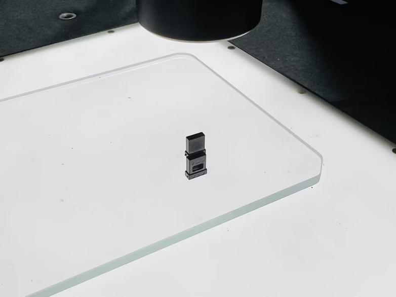
Submicron Positioning of a 0.025 mm Fiber Hole | POMEAS
How to image a 0.025 mm fiber optic hole with sharp edges and position it below 1 µm: 65 MP camera, infinity-corrected optics and a flat parallel backlight with a half-angle below 0.1°.
How to Image and Submicron-Position a 0.025 mm Fiber Optic Hole
In short: a 0.025 mm diameter hole can be imaged with sharp edges and located repeatably to better than 1 µm by combining three elements: a 65 MP global-shutter industrial camera (3.2 µm pixel), an infinity-corrected, field-corrected optic suitable for apochromatic objectives, and a flat parallel backlight with a half-angle below 0.1°. This application note explains why conventional illumination schemes fail at this scale, how the required resolution is dimensioned, and which configuration was used in the real project.
Key project parameters
| Parameter | Value | Source |
|---|---|---|
| Hole diameter | 0.025 mm (25 µm) | Project record |
| Diameter of the fiber to be inserted | 0.020 mm (20 µm) | Project record |
| Required positioning accuracy | ≤ 1 µm | Project record |
| Sensor resolution | 9344 × 7000 px (65 MP) | Official product documentation |
| Pixel size | 3.2 µm | Official product documentation |
| Working field of view | 7 mm | Project record |
| Object-side resolution per pixel (calculated) | ≈ 0.75 µm/px | Own calculation from FOV (estimate) |
Background: why 25 µm is a borderline case
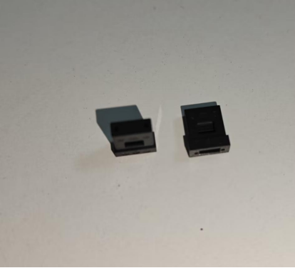
The end user is a fiber optic product manufacturer; the requirement came from the maker of the automatic assembly equipment, which had to insert a 20 µm fiber into a 25 µm hole. The mechanical margin between the two is only 2.5 µm per side, so machine vision cannot afford any drift in estimating the hole center: the full positioning requirement is ≤ 1 µm throughout the insertion operation.
Why conventional schemes fail
Three technical reasons explain why the integrator's earlier trials did not reach the target repeatability:
- Insufficient sampling resolution. With large-pixel, low-resolution cameras the edge of the 25 µm hole is represented by very few pixels and appears blurred; sub-pixel edge extraction loses statistical meaning and repeatability degrades far above 1 µm.
- Illumination with a diffuse component. Conventional ring or area sources produce scattered reflection and edge halo on a translucent plastic part: the measured edge shifts with brightness and position, and the calculated center fluctuates from cycle to cycle.
- Limited installation space. The assembly station must work at a short distance while keeping illumination uniform and contrast high, which rules out bulky optics or long working distances.
System configuration
| Component | Specification used | Source |
|---|---|---|
| Industrial camera | 65 MP global-shutter CMOS, 3.2 µm pixel, 9344 × 7000 px, 10G Ethernet transmission | Official product documentation |
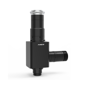
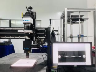
| Optics | HD objective with M58 mount, infinity-corrected optical design, compatible with flat-field apochromatic objectives up to 2", integrated coaxial optical path | Official product documentation |
| Illumination | Flat parallel backlight, parallelism half-angle < 0.1°, uniformity of the useful area > 90 % | Official product documentation |
The calculation that fixes the design
The single figure that decides whether the sensor "sees" the hole is the resolution per pixel projected onto the object:
Resolution per pixel = FOV ÷ horizontal pixels = 7000 µm ÷ 9344 px ≈ 0.75 µm/px (estimate calculated from the documented FOV).
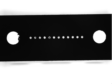
At 0.75 µm per pixel, the 25 µm diameter is sampled with more than 33 pixels and the 2.5 µm margin per side with more than 3 pixels: enough for sub-pixel edge extraction. The global shutter, in turn, removes the "jelly" distortion caused by vibration of the insertion mechanism, so that every image used for the center calculation is undistorted. The parallel backlight with a half-angle < 0.1° is the piece that closes the system: by illuminating almost in collimation, the gray transition at the hole edge is narrow and stable, and the edge centroid no longer depends on brightness or on the position of the part.
Project result
According to the project record, the system imaged the 0.025 mm hole stably with sharp edges and high contrast, and guided the insertion mechanism within the ≤ 1 µm positioning requirement, removing the reject-rate bottleneck that conventional schemes had carried.
Decision chain for your own application
- Smallest feature to measure → dimension the FOV and require at least 3–5 pixels across the critical detail (the usual sampling rule).
- Target resolution per pixel → sensor pixel ÷ system magnification; if it falls short, increase resolution or magnification, do not crop the FOV.
- Edge type → translucent parts or critical edges: parallel backlight (half-angle < 0.1°); opaque surfaces with relief: coaxial or bright-field light.
- Motion or vibration during capture → global shutter is mandatory.
- Available space → check mount and working distance before fixing the optics (here: M58 with objectives up to 2").
Frequently asked questions
The most common questions about this application are answered below; for an evaluation of your specific part, contact our technical team.
Related products
- POMEAS industrial lenses — infinity-corrected optics and precision objectives.
- Machine vision lighting — flat parallel backlights and area sources.
- Industrial cameras — high-resolution global-shutter sensors.
📖 Also available in: 中文 · Español · Français · Русский · العربية

Subscribe to Our Newsletter
Simply enter your email to receive the latest news and insights from Pomeas. Stay connected with Pomeas and be the first to discover new innovations in optical excellence.


